
Monitoring Gas Turbines Using Speedtronic Mark VI Control Systems
Gas turbine protection systems consist of a number of subsystems, including several run during each stop and normal startup. Other systems and components operate strictly during emergencies and abnormal operating conditions.
The most common type of failure on gas turbines is that of a sensor or the wiring of sensor protection systems, which are configured to detect an alarm.
If the condition is severe enough to completely disable the protection, the turbine will be triggered. It will also respond to more complex settings such as speeding, over-temperature, high-vibration monitoring of combustion and flame loss.
The examined gas turbine considered in this article is a GE MS3002, a mechanical drive machine with double shaft and single-cycle. It uses an actual gas turbine and consists of an axial compressor with 15 floors, six arranged combustion chambers to (90°) to the axial intake, a high-pressure turbine single floor (first floor), which drives the compressor and auxiliary equipment, as well as a low-pressure turbine (second floor), which drives the load.
The regulation of this turbine is made by start-control functions: sensors monitor the speed of the turbine, the exhaust temperature, compressor discharge pressure and other parameters to determine the operating conditions of the unit. When it is necessary to modify the conditions of operation – due to changes in load conditions or environmental – the regulation is done by control modules installed to the supervision of the gas turbine.
For this article, we studied the speed of the turbine (high and low pressure), vibration (the first tier and fourth tier) and the temperature (exhaust and the wheel space). We used the Speedtronic Mark VI system, which contains a number of systems, controls, protections and timings designed to ensure reliable and safe operation of the MS3002 gas turbine.
Control System
The start of control is passed to the turbine from “speed zero” to safe operating speed by supplying the right amount of fuel to establish the flame speed in a way that minimizes the fatigue cycle down. This requires an adequate sequence of control signals to the accessory device and the start of the fuel-regulating system.
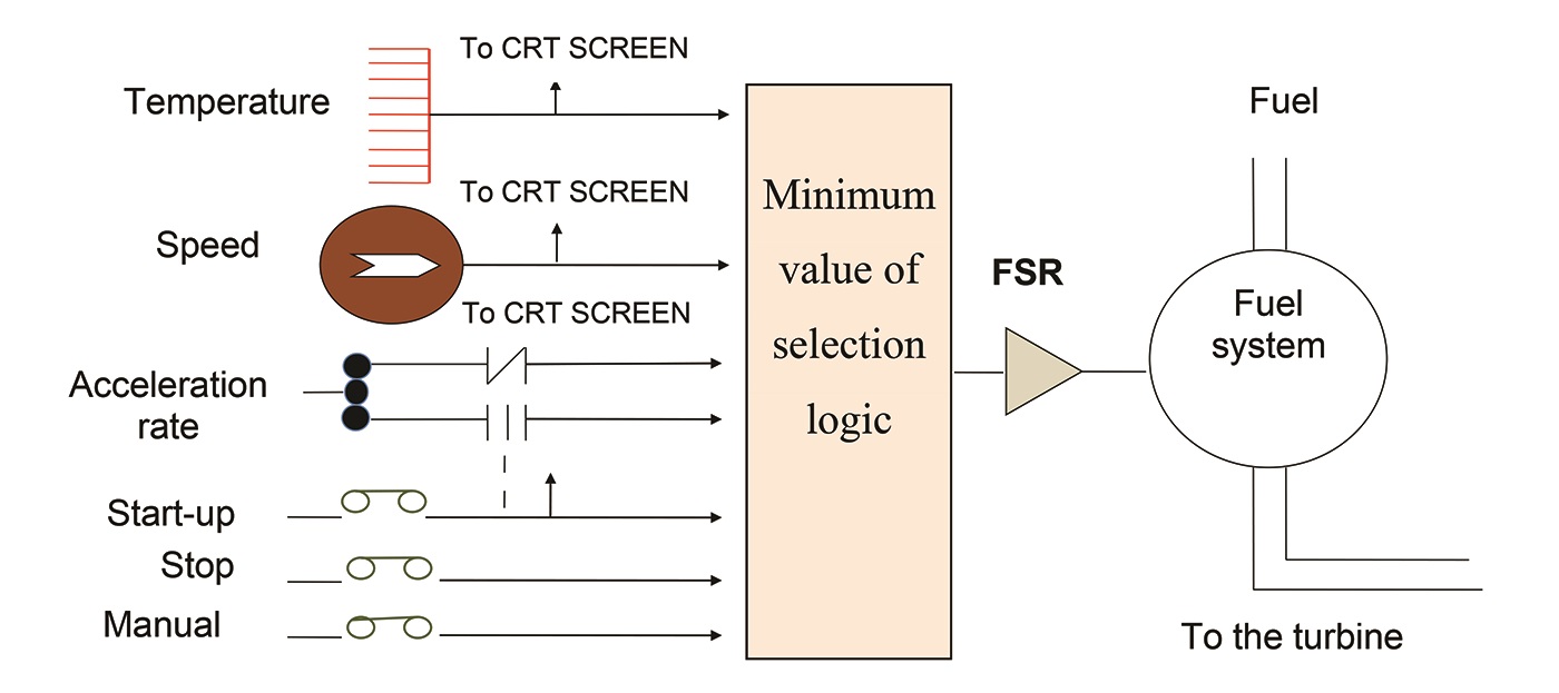
Since a successful startup depends on proper operation of the turbine equipment, it is important to check the status of selected devices in the sequence. A significant amount of control logic circuits is associated not only with operating control devices, but with valid protection circuits and obtaining permissive conditions before continuing. This ensures the control during operation of the turbine (Figure 1).
For the control system of the fuel gas, the turbine control system will change the flow to the combustion chambers in response to the fuel stroke reference signal (FSR). The machine starts with the servo-drive system, wherein the setpoint is compared with the feedback signal and converted to a valve position.
In this task, some of the protective systems and components operate through the protection circuit and master control Speedtronic in the control system, while other entirely mechanical systems operate directly on the turbine components. In each case, there are two essentially independent paths to stop the flow of fuel – the control valve of the fuel (RST) and the inlet of the liquid fuel valve (FSV).
Each protection system is designed independently of the control system to avoid the risk of the control system disabling protective devices. The Speedtronic Mark VI is designed to protect the gas turbine against any damage caused by over-speed of the turbine rotor. Under normal operating conditions, the rotor speed is controlled by the speed control.
Industrial Application
The gas compressor station, SC2 M’SEKA, Algeria is composed of several hardware and complex industrial facilities. We examined a gas turbine installed at this location (Figure 2).
[inline:Gas_turbine_2.jpg]
Figure 2: The site of gas compression station SC2 M’SEKA, Algeria.
Measuring and control instruments installed in the station to track the status of the machines allowed for the acquisition of direct data.
An over-temperature system protects the gas turbine against damage caused by a spark. This relief system operates after a failure of the temperature regulating system (Figure 3).
[inline:Gas_turbine_3.jpg]
Figure 3: Over-temperature protection.
Under normal operating conditions, the exhaust temperature control system acts to control the flow of fuel when the ignition temperature limit is reached. However, in certain failure modes, the exhaust temperature and fuel flow rate may exceed the control limits. The constant speed control is obtained with the control set to 99% for the minimum value and 100% for the maximum speed. In this case, the area of the turbine flow rate is raised to the maximum.
To monitor the level of vibration sensors and the set point by the breeder switch mounted on the calibration card, a range switch measures the vibration velocity (0-15 inches per second).
To control the exhaust temperature, 12 thermocouples were installed in the exhaust chamber (Figure 4). The data of the thermocouples were compensated for and their average taken. The cabinet average thermocouple operates on the output signals from the exhaust to be averaged to provide temperature control in the exhaust system and to the alarm system and latching.
[inline:gas turbine_4.jpg]
Figure 4: The location of the temperature sensors in the box.
Figure 5 shows the evolution of the thermocouple temperature 7 (TTXD1). This is the same behavior seen in other thermocouples, and there is a directly proportional relationship between TNL and the average exhaust temperature.
[inline:Gas_turbine_5.jpg]
Figure 5: Evolution of the temperature of thermocouple (TTXD1).
To control the temperature of the wheel space, there are two wheels separated in the gas turbine – the first-stage (the high-pressure wheel), which drives the axial compressor, and the second-stage (low-pressure wheel), which drives the load. The two wheels are arranged in series in the turbine, but are mechanically independent so that both turbines can operate at different speeds.
Thermocouples that measure the temperature of the rear wheel area of the first floor (Figure 6), and the front wheel space of the second floor are located in the end facing the diaphragm.
[inline:gas turbine_6.jpg]
Figure 6: Location of the thermocouples in the examined system.
Figure 7 shows the evolution of the temperature of space wheel, from thermocouples first floor (HP) and the second floor (BP).
[inline:Gas_turbine_7.jpg]
Figure 7: Variation of temperature of the wheel space.
After the delay for heating, the system acts on the fuel valve by modulating the fuel FSRACC signals (acceleration) and FSRT (temperature) to speed up the HP turbine with an acceleration rate of 2.8° C/sec. As the fuel increases, the HP turbine accelerates and about 40% the LP turbine starts.
[inline:Gas_turbine_8.jpg]
Figure 8: Variation of the control signal to the fuel flow FSRACC.
The load on the turbine is controlled by adjusting the fuel to bring the speed of the low-pressure shaft to a predetermined operating point. The speed of the high-pressure shaft is also measured for all the load-operating range. The speed of the shaft is used to determine the distribution of the energy available between the high-pressure and low-pressure shafts.
Conclusion
The Speedtronic Mark VI system is designed to protect the gas turbine against any damage caused by rotor over-speed of the turbine, under normal operating conditions.
The over-speed system cannot be requested unless the other systems have failed. Because of the ease of implementation and ability to process the imprecise, it is possible to obtain good performance from the monitoring and control of different turbine parameters, ensuring the continued optimum operation.
Ahmed Hafaifa is senior lecturer in industrial process automation and control engineering at the Science and Technology Faculty at the University of Djelfa, Algeria. He has supervised several masters’ and doctoral students and has written several papers in archival journals. Kouzou Abdellah earned a state engineering degree and a doctorate from the University of Tiaret, Algeria and University of Boumerdes, Polytechnics Superior National School, respectively. He is an associate professor with Djelfa University in Algeria where he is president of the Scientific Council of the Sciences and Technology Faculty. Previously he worked as a researcher with Technische Universität of Muenchen, Germany.
Authors: Mr Benrabeh Djaidir is a doctoral student in automation system at the University of Djelfa in Algeria and a member of Applied Automation and Diagnostics Industrial laboratory. He holds a master’s degree in industrial instrumentation maintenance. His main focus is analysis of failure modes and failure of a gas turbine.
Related News
Related News

- Keystone Oil Pipeline Resumes Operations After Temporary Shutdown
- Freeport LNG Plant Runs Near Zero Consumption for Fifth Day
- Biden Administration Buys Oil for Emergency Reserve Above Target Price
- Mexico Seizes Air Liquide's Hydrogen Plant at Pemex Refinery
- Enbridge to Invest $500 Million in Pipeline Assets, Including Expansion of 850-Mile Gray Oak Pipeline
Comments