
August 2023, Vol. 250, No. 8
Features
Residual Stress in Predicted Failure Pressure Calculation
By Michael J. Rosenfeld, Chief Engineer, RSI Pipeline Solutions LLC, and Scott Fannin, Principal Engineer, Pacific Gas & Electric Company (PG&E)
[Editor’s note: This article on residual stress and predicted failure on pressure calculation is being presented in two parts, with the second installation appearing in P&GJ’s September issue.]
(P&GJ) — Pipeline safety regulations require performing a calculation of the predicted failure pressure (PFP) of defects as part of an engineering critical assessment. Whether to include residual stress from pipe manufacturing, and selecting the magnitude of residual stress, can significantly affect the outcome of the PFP calculation. Guidance for accounting for residual stress is inconsistent.
A survey was performed of several dozen research reports describing testing and analyses of residual stresses induced by the pipe manufacturing process for various types of line pipe. A simple method for determining whether to account for residual stress, and if so, at what magnitude, has been devised for various categories of electric resistance weld (ERW) pipe, and also for non-ERW pipe.
There are several scenarios in which the operator of a natural gas or hazardous liquid pipeline must calculate the PFP including maximum allowable operating pressure (MAOP) verification, pipeline maintenance, and integrity management work.
Recent regulations in 49 CFR 192, §192.712, further specify that evaluations of the PFP of crack-like features be performed using valid fracture mechanics models or methods that appropriately account for material properties and boundary conditions. Residual stresses are not mentioned in the regulations but might be considered as a boundary condition if they are expected to influence the PFP.
If so, then further questions arise as to which pipe types contain residual stresses, the magnitude of residual stresses, and the technique for accounting for the stresses in the PFP evaluation.
This paper addresses those questions by reviewing the manufacturing steps involved in producing various types of line pipe, reviewing the significance of pipe vintage, compiling the results from tests and studies that have determined the magnitudes and patterns of residual stresses in pipe, identifying the expected residual stress magnitude by type of pipe and evaluating the effect of residual stress in the PFP calculation.
Manufacturing Steps
The ERW pipe manufacturing steps that inherently affect the strain history and therefore could introduce or affect residual stresses, include:
- Skelp uncoiling and leveling
- Skelp roll forming
- ERW seam welding and squeeze-out
- Seam annealing
- Diameter sizing (usually by multiple stages of diameter reduction, less often by diameter
- expansion)
- Rotary straightening and rounding
- Hydrostatic pressure testing to 75%-85% SMYS in the case of API 5L and 5LX pipe
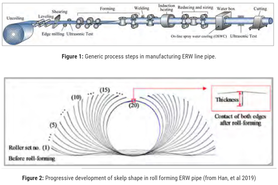
The process steps are shown schematically in Figure 1.1
The steps may differ among manufacturers.
Seam annealing for intermediate and larger sizes is usually focused at the seam and not on the whole pipe as shown. Some smaller sizes undergo stretch-reduction size. Not shown are rotary straightening stages, which are usually performed with small or intermediate sizes after the sizing stages. Figure 1 overlays the sequential development of the roll-formed pipe section.
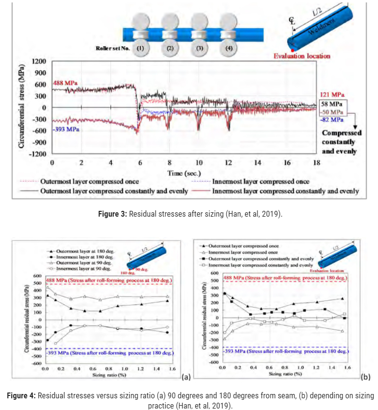
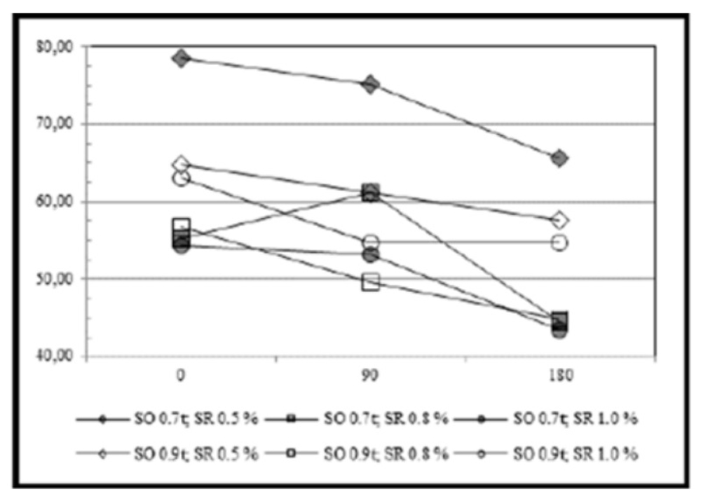
Small- and medium-sized ERW is radially squeezed through multiple sizing reduction stands, which introduce strain reversal cycles at each stand and significantly reduce residual stress2 (Figure 3). The amount of reduction is affected by the number of reduction stands, Figure 4 (Han, et al 2019) and the relative diameter-sizing reduction ratio3, which can vary from 0.5% to 1.5%.
Residual stresses differed at 90 degrees and 180 degrees from the seam. Squeeze-out during welding (which refers to how much metal flows into the seam upset) also affects residual stress (Harianto, et al). The squeeze-out ratio can vary from 0.5 to 1.0. Residual stresses were found to vary around the pipe circumference even after sizing and pressure testing4, had a relatively flat distribution through-wall after all forming steps, and tended to increase with decreasing D/t.5
DSAW Pipe
Pipe manufactured with double-submerged arc-welded (DSAW) seams may have longitudinal (SAWL) or helical (SAWH, colloquially, “spiral”) seams. The SAWL pipe manufacturing steps that inherently affect the strain history, and therefore could introduce or affect residual stresses, include:
- Plate edge-crimping
- Bend rolling or hydraulic pressing of the plate to cylindrical shape
- Seam welding
- Diameter sizing by mechanical or hydraulic expansion (when practiced)
- Seam weld heat treatment
- Straightening
- Hydrostatic pressure testing, 85%-90% SMYS for API 5L and 5LX pipe
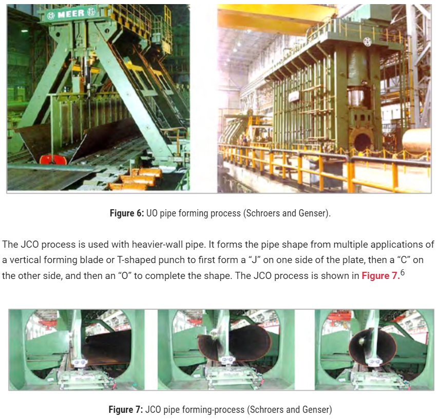
The three methods of forming SAWL pipe are the UO process, the JCO process, and three-roll bending (3RB). UO and JCO involve initial edge crimping to enable the plate edges to join at a slight angle because it is difficult to form curved plates at the edges. The roll bending process may or may not involve edge crimping. The UO forming process (Figure 6).
The JCO process is used with heavier-wall pipe. It forms the pipe shape from multiple applications of a vertical forming blade or T-shaped punch to first form a “J” on one side of the plate, then a “C” on the other side, and then an “O” to complete the shape. The JCO process is shown in Figure 7.6
SAWL pipe may be mechanically expanded to final size using a device consisting of multiple shaped segments that act against the inside of the pipe. UO and JCO pipe that incorporates expansion in the manufacturing process is referred to as UOE and JCOE pipe. Historically, hydraulic pressure has also been used to expand line pipe. Not all UO, JCO or 3RB pipe manufacturers have always implemented expansion.
Residual stress patterns have been found to vary cyclically around the JCOE pipe depending on how many individual punches of the forming dies were applied7.
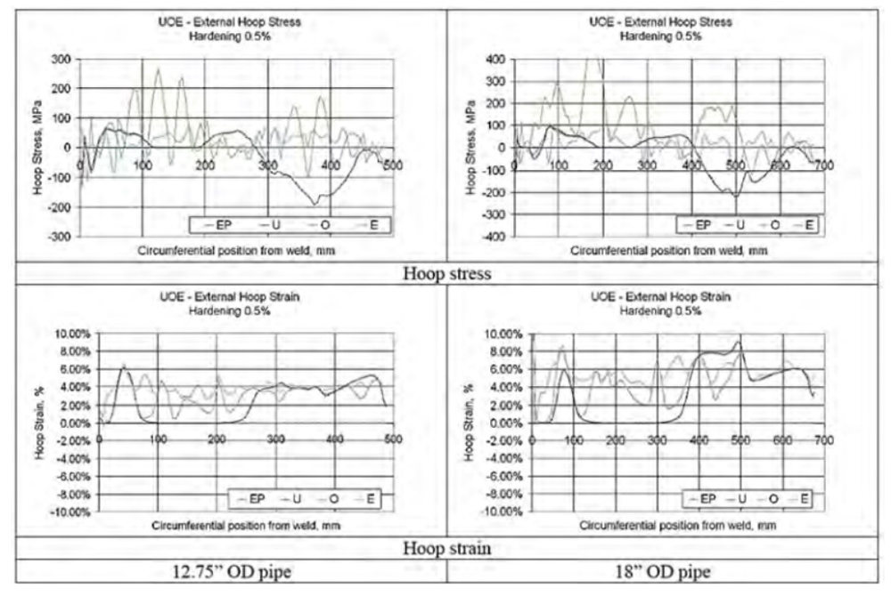
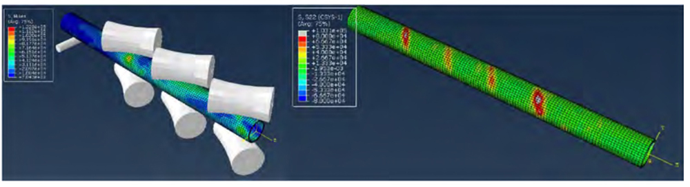
Residual stresses after forming by the UOE process were determined to vary significantly around the circumference as a function of strain hardening rates and D/t even after expansion and pressure testing (Figure 8).8
Helical Seam Pipe
The SAWH pipe manufacturing steps that inherently affect the strain history, and therefore could introduce or affect residual stresses, include:
- Skelp uncoiling and leveling
- Helical roll forming
- Seam welding
- Diameter-sizing by mechanical or hydraulic expansion (if practiced, as this appears to be uncommon)
- Hydrostatic pressure testing, 85%-90% SMYS for API 5L and 5LX pipe
The forming may consist of a simple three-roller bending process, but in some implementations the plate undergoes a plastic curvature reversal at the entry to the three-roll bender to maintain tension and alignment, introducing a complex through-wall residual stress distribution.
Expansion was not identified as a process step by most SAWH pipe manufacturer’s websites. The “History of Line Pipe Manufacturing in North America” identifies Stel pipe (Stelco) as practicing mechanical expansion of their SAWH pipe however they are no longer in the line pipe manufacturing business.
Seamless Pipe
The seamless pipe forming steps consist of piercing the solid billet, plug mill rolling, and sizing (in compression) or stretch-reducing. These are hot forging processes with the piercing and plug mill operations performed at temperatures of1,250-1,300 C, and sizing or stretch-reducing performed at temperatures of 820-870 C, followed by air cooling, and so do not produce residual stresses.
After air cooling, the seamless pipe is passed through multi-stage rotary straighteners to round-out and straighten the tube to meet dimensional controls, introducing helical lobes of residual stress due to initial tube ovality or tube camber (Figure 9).
The magnitude of stresses vary with initial ovality, bowing and eccentricity. Furnace butt-welded and continuous butt-welded pipe are also formed hot and must meet finished product dimensional controls and so might be expected to have residual stresses like those of seamless pipe.
No studies were identified that addressed residual stresses in pipes produced by the butt-welding manufacturing processes, however.
Pipe Vintage
It has been asserted that modern manufacturing processes have largely eliminated residual stresses, but that many vintage pipelines have significant residual forming stresses.10
To assume that all “vintage” pipes have high residual stresses while modern pipe does not is inaccurate. The studies reviewed demonstrate that both modern and vintage pipe manufactured by all methods have residual stresses.
Modern pipe manufacturing has evolved significantly in the areas of steel processing, pipe material microstructures (with the resultant improvements in strength, fracture toughness, and weldability characteristics), seam welding quality, and overall product quality control. However, those improvements have little influence on residual stresses that result from forming the pipe.
The pipe forming steps that produce residual stresses are inherent to the pipe making method and have not changed very much since each respective pipe-making method was introduced.
Moreover, residual stress is not an attribute that is tested or controlled in any edition of API 5L or 5LX. Residual stresses need not be managed to meet most pipe procurement specifications.
Cold Expansion
Sizing is used to produce a finished pipe product of the correct outer dimension within the tolerances of the pipe product specification (e.g., API 5L). Sizing by cold expansion or reduction significantly affects residual stresses induced by pipe forming.
The amount of diameter expansion is typically 1% to 3%, which stresses the pipe in tension beyond the elastic limit. The expansion plastically strains the full wall thickness, redistributing and reducing the through-wall residual bending stresses from initial pipe forming significantly, and diminishing any patterns of localized or periodic residual stress.
The “History of Line Pipe Manufacturing in North America” provides useful details of manufacturing practices, such as expansion or reduction by a pipe manufacturer. Many well-known pipe manufacturers began practicing cold expansion of their SAWL pipe starting between 1948 and various years in the 1950s. However, some modern SAWL pipe manufacturers have not always practiced expansion.
Reduction sizing is a compressive process that is the reverse of expansion. It is commonly used with ERW pipe in intermediate and smaller sizes. The pipe passes through multiple sets of rollers that incrementally reduce the pipe diameter. The final diameter reduction is typically around 2%.
Pipe sizes of 6 inches or less may be stretch-reduced, where the pipe is pulled in axial tension as it passes through the size-reduction rollers. Some manufacturers practiced reduction sizing in the 1930s and many others began to do so in the early 1950s.
Sizing of ERW pipe by reduction is more common than sizing by expansion, particularly in intermediate and smaller diameters, but not exclusively so. It is apparent that methods used to form pipe today have now been in use for 70 years, if not longer.
Pressure Testing
Pressure testing, whether at the pipe mill or later, has been shown to reduce residual tensile stresses in proportion to the test pressure level.
A.O. Smith was pressure testing pipe to 90% SMYS as early as 1933 by order and for all pipe by 1940. API 5LX required NPS 10 and larger to be pressure tested to at least 85% SMYS since 1949, while pipe 20-inch OD and larger have been required to be pressure tested to 90% SMYS since 1956.
Generally, practice preceded standardization; any requirement in API 5L or 5LX reflected what was already being practiced by most manufacturers before it appeared as a requirement in the standard.
Most pipelines installed after 1955 underwent a sustained hydrostatic or pneumatic pressure test to a stress level between 50% and 100% of SMYS, either following construction or later in service.
Heat-Treatment
Post-weld heat treatment (PWHT) significantly alters residual stresses in the seam, but probably not the pipe body. An exception would be with small to medium sized ERW pipe where the manufacturer practiced full-body normalizing. API 5L and 5LX required PWHT of seams starting with the 1967 editions.
Prior to that PWHT was not required to meet the standard, but a review of the “History of Line Pipe” shows that some manufacturers of ERW and DSAW pipe were practicing PWHT by 1950. Almost all tests of “modern” ERW line pipe (typically post-1970) reported higher residual stresses in the pipe body than in the seam. ERW Oil Country Tubular Goods (OCTG) products, i.e., well casings, were manufactured to API 5CT not API 5L or 5LX.
Seam PWHT is not required in some lower-strength grades of casing. No work reporting tests of residual stresses in older vintage ERW pipe lacking seam PWHT was identified.
High residual stresses in the seam due to the thermal transients induced by the welding process might be postulated in ERW pipe that was not subjected to the PWHT process. API 5L and 5LX required seam PWHT to eliminate hard microstructures starting in 1967. This new requirement reflected the abilities of virtually all manufacturers to carry out that process by that time. Even non-PWHT ERW pipe likely underwent a size reduction operation which tended to reduce circumferential residual tensile stresses.
Considering that the major manufacturing steps that influence residual stresses, aside from seam PWHT, have not changed significantly in 70 years suggests that most vintage pipe will not have significantly higher residual stress than modern pipe. However, that does not rule out the possibility of older-vintage pipe having greater residual stress in the seams, despite some benefit from the sizing operation.
Literature Review
Forty-four (44) papers were reviewed on the subject of residual stresses in SAWL, SAWH, ERW, EFW, seamless, offshore pipe, and OCTG products. Studies included theoretical analyses (usually but not limited to FEA), destructive tests (e.g., slit rings), strain-relief measurements, and laboratory methods. One study was performed in 1977, three were performed in the 1990s, and all the rest were performed after 2000 and concerned modern pipe.
Objectives for study included understanding the distribution and magnitude of residual stresses, the effects of pipe manufacturing variables, the effects of residual stress on environmental cracking, or the effects of residual stresses on resistance to external loading in well casing or subsea pipelines.
The only study that evaluated residual stresses in what are today considered to be “vintage pipe” was the 1977 NG-18 Report No. 10411, which evaluated pipe produced between 1930 and 1973. Seam types were primarily SAWL, SAWH and flash welded, with one lap welded sample. No ERW seams were evaluated.
Stress Findings
The residual stresses in SAWL and SAWH pipe were low in the pipe body, except immediately adjacent to the welded seam. Residual stresses were predicted to be slightly greater with materials having a larger strain hardening rate than with low strain hardening rates. Both testing and analysis demonstrated an oscillation of pipe radius, wall thickness, and residual bending stress around the circumference.
The number of die-punching steps, die geometry, expander elements and other manufacturing parameters influenced the magnitude and pattern of residual stress.
The mill pressure test was demonstrated by tests and analyses to redistribute and greatly reduce residual deformations and residual stresses.
Residual stresses were measured or predicted to be somewhat greater in ERW pipe than SAWH or SAWL pipe. Residual stresses varied with pipe and manufacturing details, including D/t, seam squeeze-out ratio, and sizing ratio. Sizing usually reduces the circumference as well as reducing out of-roundness, which may introduce bending stresses that vary in repeated patterns around the pipe circumference and along the length.
Stresses tended to increase with decreasing D/t. Several researchers reported higher residual stresses in the ERW pipe body compared to the normalized ERW seam. The residual stresses reported for ERW OCTG were higher than for ERW line pipe.
Residual Stress Data
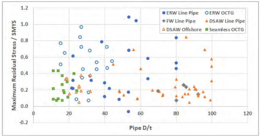
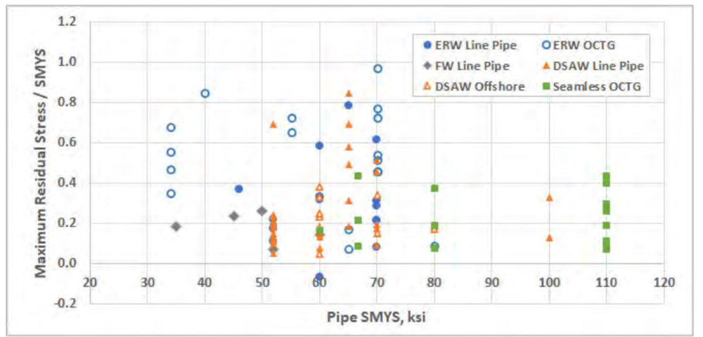
Data from these studies were compiled to determine patterns and magnitudes of residual stresses to determine appropriate residual stress levels to consider for the PFP calculation. Maximum reported residual stresses normalized to SMYS (RS/SMYS) are plotted versus D/t in Figure 10 and SMYS (Figure 11).
There is a weak tendency for maximum RS/SMYS to increase with decreasing D/t and decreasing SMYS. Differing types of pipe product exhibit weak clustering tendencies.
Several studies reported significant variation around the circumference. Studies that measured stresses at both the inside and outside surfaces reported them to be of similar magnitude but reversed sense (tension vs. compression).
That does not necessarily imply a linear variation through the wall. Most measurements were tensile at the outside surface but note that stresses could vary around some pipe in a cyclical pattern, and some seam defects can be on the inside.
Typical Stresses
Most sources reported either sufficient data to identify a maximum stress level or reported a value as the maximum. Approximately one-third of the references presented other residual stresses as they vary with position in and around the pipe. The maximum residual stresses were often localized to one quadrant of the pipe cross section and were unrepresentative of what might be considered “typical” values.
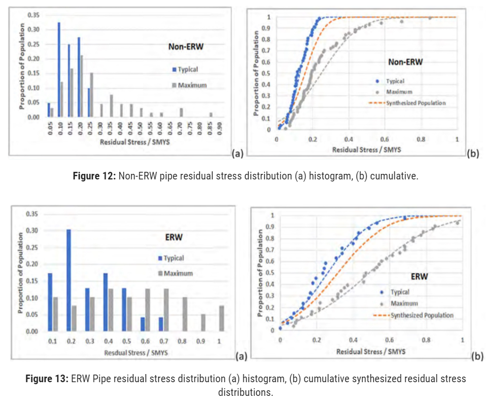
The data were segregated as apparent “maximum” and “typical” and were seen to be distinctly different populations. The typical and maximum SR/SMYS are shown as histograms and cumulative distributions for non-ERW pipe (Figure 12) and for ERW pipe (Figure 13). Each group appears to be weakly normal with subgroups that were not isolated.
(End of Part 1.)
Acknowledgment: The authors wish to thank Pacific Gas & Electric Company for their generous support of the presented work.
Editor’s note: This paper was presented at the 36th Pipeline Pigging & Integrity Management Conference, Feb. 12-6, 2023. ©Clarion Technical Conferences and Great Southern Press. Used with permission. DOI Number: 10.52202/068696-0055
References:
- Figure credit CC BY 4.0, https://creativecommons.org/licenses/by/4.0/.
- Han, S.-W., Park, Y.C., Kang, S-C., Jung, S., and Kim, H-K., “Collapse Analysis of ERW Pipe Based on
Roll-Forming and Sizing Simulations,” Journal of Marine Science and Engineering, Nov. 2019.
- Harianto, S., Susilaputra, E., Darto, P., and Fandika,A., “Effect of Squeeze-Out and Sizing Ratio to the
Residual Circumferential Stress of HFW Pipe,” MATEC Web of Conferences 269, 2019.
4.Han, S.-W., Park Y.C., Kim, H-K., and Kang, S-C., “Effect of Strain Hardening on Increase in Collapse
Pressure During the Manufacture of ERW Pipe,” MDPI, 2020.
5.Nishimura, N., Takeuchi, S., Murakami, S., and Sanui, K., “The Effect of Manufacturing Processes on
Residual Stress and Yield Stress of ERW Pipes,” 1997.
- Schroers, D. and Genser, B., “JCOE Technologies for the Economical and Flexible Production of Large Diameter Pipes”, 1st Iranian Pipe and Pipeline Conference, Tehran, 2007.
- Antoniou, K., Chatzopoulou, G., Karamanos, S.A., Tazedakis, A., Palagas, C., and Dourdounis, E.,
“Numerical Simulation of JCO-E Pipe Manufacturing Process and its Effect on the External Pressure
Capacity of the Pipe,” Journal of Offshore Mechanics and Arctic Engineering, Vol. 141, Feb. 2019.
- Raffo, J., Toscano, R.G., Mantovano, L., and Dvorkin, E.G., “Numerical Model of UOE Steel Pipes:
Forming Process and Structural Behavior,” Mecanica Computacional, v. XXVI, Oct. 2007.
- Long, X., and Moore, P.W., “The Study on ResidualStresses in OCTG and its Effect on Pipe Sour
Cracking (SSC) Performances,” NACE Corrosion Conf. & Expo, Paper No. 10919, 2018.
- Anderson, T.L., and Brown, G.W., “Effect of Residual Forming Stresses on Fracture in ERW Pipe”,
International Pipeline Conference, IPC2016-64553, 2016.

Comments