
September 2017, Vol. 244, No. 9
Features
Reciprocating Compressor Pulsations Effect on Compressor Surge Margins
The mixed operation of centrifugal and reciprocating compressors in a single compression plant has become common design practice over the last 20 years, as this arrangement can provide benefits for highly cyclical process profiles.
Conventional thinking was that a centrifugal compressor may experience some pulsations from the reciprocating compressor when in series or from both the common suction and discharge headers, but good reciprocating compressor bottle and manifold designs would result in minimal impact on the operational stability of the centrifugal compressor.
This assumption held true for small-horsepower and low-speed applications and with older, high-pressure drop and often significantly oversized pulsation-control systems. However, recent experience with mixed compressor stations utilizing large power and high-speed modern separable reciprocating compressors with modern efficient pulsation control systems shows that the centrifugal compressor can be moved into pulsation-induced operational instability for both parallel or series arrangements. This clearly presents a station design challenge, operational range limitation, and a basic safety concern.
Experimental Facility
Laboratory testing of reciprocating and centrifugal compressor mixed operation was performed in an air loop at the SwRI compressor laboratory. Figure 1 shows a schematic of the test arrangement and photos of the compressors. The testing was performed using a 50 hp single-stage, double acting reciprocating compressor mounted upstream of a two-stage, 700 hp centrifugal compressor.
The reciprocating compressor suction was open to atmosphere with an operating range of 300-1,000 rpm (5-17 Hz) using a variable frequency driver. Similarly, the centrifugal compressor was operating in a semi-open recycle loop with the loop’s discharge throttled back to atmospheric pressure, a speed range of 2,000-14,000 rpm, and maximum pressure ratio of 3:1. However, for safety reasons, the centrifugal compressor’s speed and discharge pressure were limited to 7,000 rpm and 2 bar (30 psi), respectively, for the subject test series.

Figure 1: Schematic of the test loop arrangement.
Baseline Data
All surge tests were performed with the centrifugal compressor operating at 7,000 rpm and near-ambient suction pressure to minimize the risk of damage to the compressor during the anticipated surge events. Figure 2 shows 4 Hz axial rotor vibration measured by proximity probes for no-surge vs. surge-operating conditions of the compressor.
Clearly, a significant rise in 4 Hz vibration amplitudes is observed. Similar results showing significantly elevated surge-pressure pulsations at the characteristic 4 Hz were seen from the suction and discharge dynamic pressure transducers. Thus, for all test series, the onset of surge criteria was established to be a rapid increase in 4 Hz compressor axial vibrations and suction/discharge flange dynamic pressure pulsations.

Figure 2: Axial compressor vibrations before and in surge conditions.
Impact On Surge Margin
To determine the impact of externally induced pulsations on the surge margin of the centrifugal compressor, the reciprocating compressor is operated upstream in series with the centrifugal compressor. The pulsations from the reciprocating compressor thus travel through 55 feet of varying diameter pipe before they enter the centrifugal compressor suction flange.
Some pulsation attenuation or acoustic amplification will occur in this pipe segment and must be quantified. Time domain pulsations were measured at the reciprocating compressor discharge, the centrifugal compressor suction, and the centrifugal compressor discharge.
For the testing, the centrifugal compressor was initially operated at a stable point with approximately 15% surge margin to the right of the surge line. The reciprocating compressor was then started, brought to a fixed speed, and its pressure and flow-pulsation amplitudes were recorded at the centrifugal compressor suction flange using dynamic pressure transducers and the hot-wire anemometer, respectively.
The centrifugal compressor loop recycle valve was then slowly closed until surge was clearly indicated by axial vibrations and suction/discharge pulsations. Only when the previously established surge criteria were fully met was the pulsation-induced surge point recorded. The difference between the previously recorded steady-state surge point (from the performance map) and the pulsation-induced surge point was used to calculate the difference in surge margin.
Figure 3 shows a typical test run with the reciprocating compressor running. Pressure fluctuations and compressor inlet flow are plotted vs. test recording time. In this case, the 4 Hz discharge pulsations are used as an indicator for the onset of surge. The test started at 1:55:44 p.m. with the recycle valve being slowly closed, decreasing the flow into the centrifugal compressor (red line).
At the time of 2:00:53 p.m., the 4 hertz (Hz) discharge volute pulsations are seen to increase, which corresponds to a flow of 106.5 actual cubic feet per minute (acfm), about 6 acfm away from the steady-state surge line. As the recycle valve is further closed, and the flow is further decreased, the pulsations are seen to increase, approximately linearly with flow reduction. A drastic 4 Hz pulsation increase can then be observed when the flow reaches the steady-state surge line at 100.5 acfm.
In this particular case, a gradual onset of surge can be observed well before the machine is operating near the surge line. This provides evidence that periodically unsteady flow can induce surge in a centrifugal compressor when the compressor is seemingly still operating to the right of the surge line on the performance map.

Figure 3: Test results of 4 hz pulsations and flow vs. test time.
Operating Map Ellipse
For the 106 acfm surge onset case (with the reciprocating compressor running), the pulsations entering the centrifugal compressor just before the onset of surge were measured to be 44 acfm peak-to-peak in flow and 0.058 psi peak-to-peak in pressure. One can thus plot an ellipse of the actual operating point of the centrifugal compressor based on its fluctuating suction flow and pressure conditions.
This operating map ellipse defines the cyclically unsteady operating point of the compressor on its performance map. Specifically, the ellipse closely represents the true operating range of the compressor on the compressor map, since with periodically transient cyclic suction/discharge operating pressures, the compressor operating point will never be on its time-averaged or steady-state operating point.
One should note that pulsations from a reciprocating compressor are not perfectly sinusoidal. Still, the assumption of an elliptical shape significantly simplifies further analysis and was found to not introduce significant error when used as a design tool.
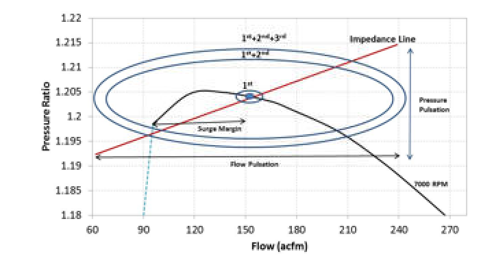
The operating map ellipse can be further refined by showing the different pulsation frequency orders as shown in Figure 4. In this example, the reciprocating compressor running speed was 615 rpm, the excitation frequency was 10.25 Hz, and a surge margin differential of 41.2% was found.
Clearly, the compressor surged before it had reached its peak pressure ratio on the 7,000 rpm speed line. The 1st order ellipse shows the induced pulsation only from the pulsations at the 10.25 Hz operating frequency (running speed), the 1st and 2nd order ellipse show energy from both first and second orders (up to 20.5 Hz), and the 1st, 2nd, and 3rd order ellipse show energy up to 30.75 Hz for all three orders.
Pulsations from reciprocating compressors have significant higher order frequency content when the cylinders are double-acting since the pulse wave form is not sinusoidal. Thus, in this case, most pulsation energy was in the second order as can be seen by the much larger 1st and 2nd order operating map ellipse.
The energy from the 3rd order does not significantly increase the radius of the operating map ellipse (1st, 2nd, and 3rd) as it does not contain significant pulsation energy. Fourth and higher order frequency energy content was also found to be negligible. In most cases, for reciprocating compressors operating below 1,500 rpm, almost all surge-relevant pulsation energy is contained in the frequency orders below 75 Hz.

Figure 4. Operating map ellipses for different pulsation frequency orders.
Test Results
For very high pulsation amplitudes, surge margin reductions above 40% were seen. However, for more moderate pulsation levels, similar in range to pulsation to mean line pressure ratios found in industrial compressor station applications, surge margin reductions were closer to 15-25%. The flow and pressure pulsation data was utilized to determine the operating map ellipse and the area of the ellipse that crosses the surge line. For all test cases, this area was found to be approximately 30-35% of the total operating map ellipse’s area.
To validate current engineering tools and to improve the compressor station design process, the test data was benchmarked to SwRI’s 1-D time domain transient pipe flow analysis code (TAPS). From a compressor station design perspective, the critical question is whether the 1-D transient piping codes currently utilized by the industry can adequately predict the suction/discharge pulsations on a centrifugal compressor such that the induced pressure and flow fluctuation accurately represent the characteristic ellipse around its steady-state operating point on the compressor’s performance map.
Thus, a number of numerical studies were performed using the model of the complex piping system of the previously described test facility and compressor operating characteristics for comparison with test data. TAPS provides a pulsation analysis by solving the 1-D time-domain Navier-Stokes equations of fluid flow through complex piping networks for highly transient flows and is commonly utilized to analyze piping acoustic problems in compressor stations.
Figure 5 shows a frequency domain comparison between test data for the 480 rpm speed reciprocating compressor case vs. pulsation amplitude and frequency predictions from TAPS. The predictions are seen to match test data to within 6%. Having the capability to numerically analyze pulsating flow in the complex piping and equipment network of a mixed compressor station is imperative for design work and safe operation.

Figure 5: Comparison of centrifugal compressor inlet pulsation from taps predictions vs. test data.
Design Recommendations
To avoid centrifugal compressor surge or operating range reduction due to pulsations from a reciprocating compressor in a mixed compressor station, it is worthwhile to establish some basic engineering guidelines for station design. The most conservative design rule is simply to require that the centrifugal compressor’s operating map ellipse does not cross the surge line for all operating conditions of the compressor station. However, this rule may be excessively conservative and could result in a significantly reduced operating range of the centrifugal compressor.
A more pragmatic approach is to set a threshold interference level between the operating map ellipse and the surge that results in measurable surge. From the results of the above testing, it was found that surge was consistently identified when approximately 30% of the area of the operating map ellipse had crossed the surge lines for all suction/discharge pulsation frequency orders under 75 Hz.
Conclusions
Pressure suction/discharge pulsations in pressure and flow can move a centrifugal compressor into surge and affect its performance. In mixed pipeline compressor stations where centrifugal compressors operate in series or parallel with reciprocating compressors, this is of special concern for operational range and safety reasons and must be considered during the design process. Thus, testing of reciprocating and centrifugal compressor mixed operation was performed in an air loop at the SwRI compressor laboratory.
The specific goal was to quantify the impact of periodic pressure and flow pulsation originating from a reciprocating compressor on the surge margin and performance of a centrifugal compressor. The principal findings of the above-presented research are summarized below. Specifically, test and analysis results provided clear evidence that:
- External pulsations applied to the suction or discharge flange of a centrifugal compressor reduce its surge margin significantly.
- The geometry of the piping system immediately upstream and downstream of a centrifugal compressor can have significant impact on the surge margin reduction (surge margin differential).
- The reduction of surge margin due to external pulsations is a function of the pulsation’s amplitudes and frequencies at the compressor suction and discharge flange. High suction flange amplitudes at low frequencies significantly increase the risk of surge. Surge margin reductions (differentials) over 40% were observed during testing.
- Using the transient operating map ellipse of the centrifugal compressor is a useful tool to identify the potential onset of surge. From the operating map ellipse surge margin differential can be calculated for various orders of pulsations.
- Surge was consistently identified when approximately 30% of the area of the operating map ellipse had crossed the surge lines for all suction/discharge pulsation frequencies orders.
- A transient time domain 1-D Navier-Stokes pipe network analysis model was able to accurately predict suction/discharge pulsations into a centrifugal compressor and thus, its operating map ellipse. Using the above-described basic design rule, these pressure/flow pulsation amplitude predictions can be related to surge margin differential.
When designing compressor stations, it is critically important to have a full understanding of the impact of the station’s piping system on the compressor dynamic behavior. Both acoustic resonance and system impedance are functions of the entire piping system connected to the compressor. Thus, a careful acoustic and impedance design review of a compressor station design should be performed to avoid impacting the operating range of the machine and to properly balance these needs against the surge control system design requirements.
Authors: Dr. Klaus Brun is program director of the Machinery Program at SwRI. His experience includes positions in engineering, project management, and management at Solar Turbines, General Electric, and Alstom. He holds six patents, authored over 150 papers, and published two textbooks on gas turbines. He is the Executive Correspondent of Turbomachinery International Magazine and an Associate Editor of the ASME Journal of Gas Turbines for Power.
Sarah Simons is a research scientist in the Fluid Machinery Systems Section at SwRI). In her five years at SwRI, she has gained experience in the fields of acoustics, vibrations, and piping design. She has performed many acoustic, thermal, and modal analyses of complex existing and new machinery piping systems (for both compressors and pumps) with the aid of commercial and in-house digital design tools. She has written and co-authored papers on the subject of acoustics, pulsations and vibration in the piping systems of compressors and pumps. Simons has a degree in mathematics from the University of California-Davis.
Dr. Rainer Kurz is the manager, Systems Analysis, at Solar Turbines Incorporated in San Diego, CA. His organization is responsible for analyzing compression requirements, predicting compressor and gas turbine performance, for conducting application studies, and for field performance testing. Kurz has written numerous publications about turbo-machinery related topics and is an ASME fellow and member of the Turbomachinery Symposium Advisory Committee. He received the degree of a Dr.-Ing from the the Universität der Bundeswehr in Hamburg, Germany.

Comments