
March 2017, Vol. 244, No. 3
Features
Monitoring Key to Developing Rigorous Corrosion-Protection Program for Gas Storage
Recent recommendations from the federal Department of Energy (DOE) regarding corrosion-protection programs for natural gas storage will likely require action on the part of operators around the country. As Ernest J. Moniz, the outgiong Secretary of Energy, wrote in the introductory pages of the DOE Final Report of the Interagency Task Force on Natural Gas Storage Safety1, “Gas storage operators should begin a rigorous evaluation program to baseline the status of their wells, {and} establish risk management planning…”
For many operators already understaffed and overburdened with regulatory requirements, the task of developing such a program will fall to outside resources.
In keeping with the industry’s move to a more integrated pipeline safety culture, several new recommendations – including those from the DOE – are affecting gas storage operations. Recommendations include PHMSA Advisory Bulletin (ADB-2016-02) on Safe Operation of Underground Storage Facilities for Natural Gas; the subsequent Interim Final Rule (PHMSA 2016-0016), which adopted both API 1170 “Design and Operation of Solution-mined Salt Caverns Used for Natural Gas Storage” and API 1171 “Functional Integrity of Natural Gas Storage in Depleted Hydrocarbon Reservoirs and Aquifer Reservoirs”; and relevant state regulations.
In addition to becoming a regulatory requirement, a risk evaluation of underground storage and gathering line assets is a prudent business decision.
A comprehensive underground storage risk-evaluation program should consider areas of potential risk, including internal and external corrosion, among other aspects. The risk-evaluation plan should also include aboveground assets such as tanks, wellhead equipment, gathering line piping, station piping, and equipment – where corrosive constituents may accumulate. A robust risk-evaluation plan should also integrate monitoring methods for ongoing assurance.
There are three principal types of underground storage sites in the United States – depleted natural gas or oil fields, aquifers, and salt caverns. Depleted fields are the most prevalent and found throughout the US; aquifers are concentrated in the Midwest; and salt caverns are found mostly in the South near the Gulf Coast. Each type poses unique considerations relating to corrosion.
Internal Corrosion & Monitoring
Internal corrosion is attributed to over half of onshore gathering line failures2. In addition to the common forms of corrosion, particular concern in storage fields may include:
- Under-deposit corrosion, a form of localized corrosion featuring deep penetration, occurring under or around deposits of collection of material.
- Velocity/flow-related corrosion including erosion corrosion which can occur when particulates coming up from the well cause heavy abrasions.
- Environmentally Assisted Corrosion (EAC), which includes Hydrogen-Induced Corrosion (HIC), Hydrogen Embrittlement (HE), and Stress Corrosion Cracking (SCC).
- Microbiologically Induced Corrosion (MIC), caused when the biological processes of microorganisms alter the metal’s surface by physical or chemical means.
Internal corrosion conditions can accelerate quickly in underground storage and gathering line assets. Operators are advised to establish and heed the warnings of a robust monitoring system. With so many variables associated with internal corrosion, operators are often well-advised to select an outside consulting team with extensive corrosion-control experience and metallurgical expertise.
Because each storage field is unique, an internal corrosion-monitoring program should begin with a survey of all assets including injection/withdrawal (I/W), observation, and disposal wells along with associated equipment and gathering lines that connect the wellhead to the storage facility. Monitoring locations can include vessels, piping low points, stub ends, drips, I/W wells, and receivers which can also contribute to the evaluation process.
A wide range of complementary testing methods should be considered before defining the monitoring system for each storage field and its geological and physical features.
Non-destructive testing at gathering system locations where corrosion is most likely to occur provides direct measurement of internal corrosion to support other testing methods. This can be performed on aboveground equipment or piping that is easily accessible for routine monitoring.
ILI, which is a popular method to assess longer transmission lines, can and has been applied to storage gathering lines. However, the complexity of gathering systems can make pigging a challenge. Gathering systems can consist of various diameter pipe, with main gathering lines ranging from 6-16” and lateral pipe connecting the wells to the main line being anywhere from 2-6”.
Despite this challenge, the pigging process affords some benefits for corrosion monitoring. Besides helping remove liquid and/or debris from the gathering lines, pigging can provide information regarding the internal conditions of the pipe when the material collected in the pigging process is sampled and tested.
Internal corrosion data, once collected, can be supported by direct examinations that can include ILI validations and visual inspection. Effective visual inspection should include removal of any scale and cleaning of the pipe surface before making any determinations.
External Corrosion & Cathodic Protection
Pipeline coatings, common on horizontal lines, are the first and foremost defense against external corrosion for pipelines. Cathodic protection (CP) complements these coatings in ensuring asset protection. For bare steel downhole casings, a more robust CP system is necessary. While either or both galvanic anode and impressed current systems can be used in CP, differing levels of protection are likely needed for the pipeline vs. downhole assets.
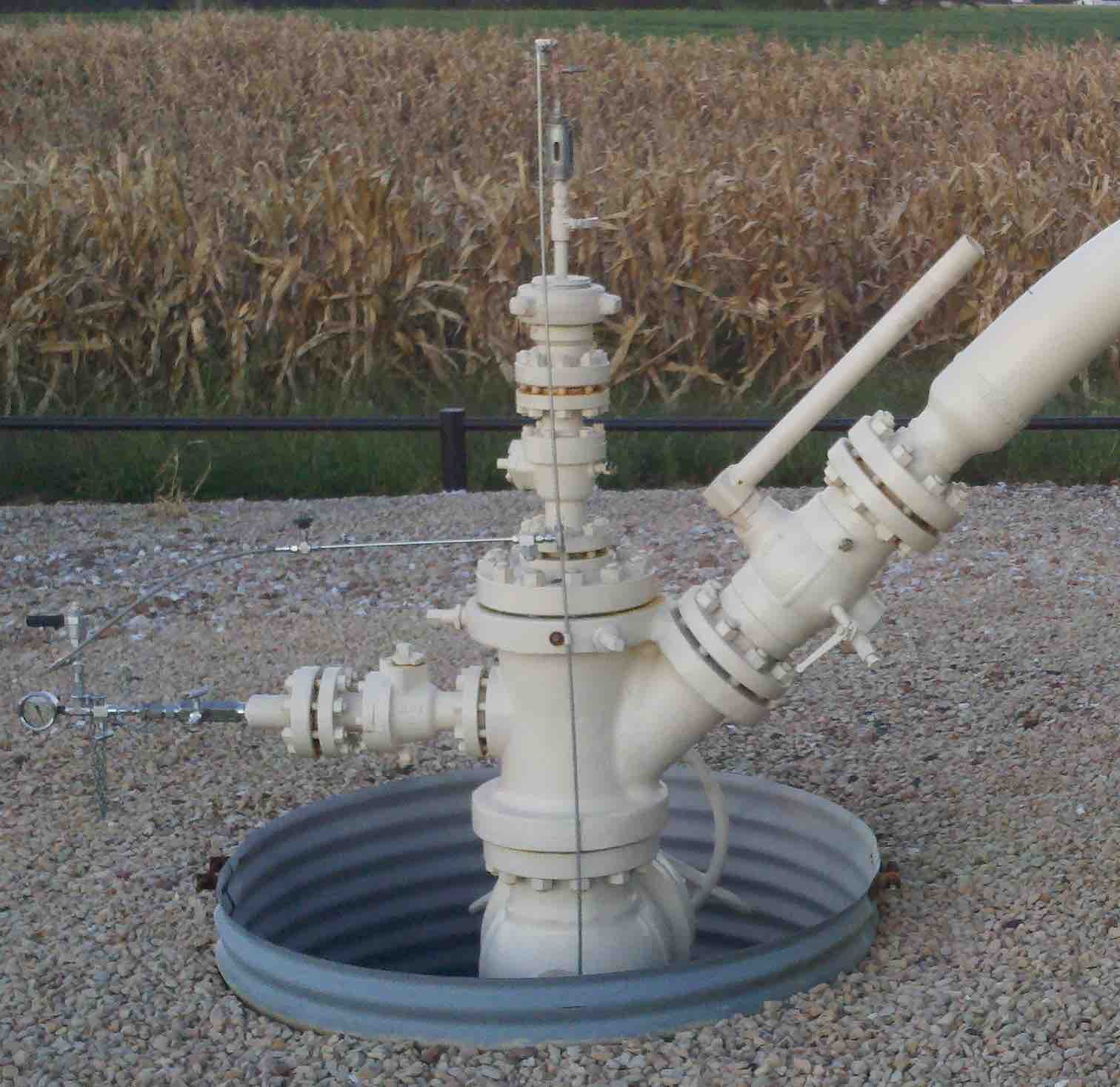
Establishing the current density criteria in a horizontal pipeline is a very different process than one applied to a storage field. Furthermore, current flow does not discriminate among assets (see Figure 1). Operators are advised to be fully aware of all assets and deploy a CP system that is holistic.

The space constraints associated with storage assets may lead to multiple ground-bed configurations. Operators should take care to ensure that ground beds are a suitable distance away from the pipe that requires protection. However, the space constraints within a storage field may make this difficult to achieve. In addition, the very nature of a storage field suggests multiple ground penetrations and a network of interconnecting pipelines.
Such conditions may necessitate the need for several ground beds to protect specific areas of the storage field. Furthermore, downhole assets may pass through several geological strata, each with different soil characteristics and resistivity. Thus, the amount of CP necessary for downhole and surface-level (i.e. gathering pipelines) assets may differ significantly.
Several factors should be taken into consideration before designing the appropriate corrosion-protection system to guard against external corrosion at a storage field facility. These factors may include:
- Environment corrosivity
- Soil structure and resistivity
- Bare or coated asset and coating quality
- Metal or alloy of asset
- Asset size (diameter, length, wall thickness, etc.)
- Presence of other metallic structures and stray current
- Historic CP measures or existing systems
A CP expert can determine the proper CP current density level required for each structure. The application of CP up to some level is beneficial – with the goal to achieve a net current pickup along the entire wellhead length. Beyond this level, however, geologic changes along a vertical well configuration may actually create conditions where the net current pickup is reversed – an example of too much of a good thing becoming a negative.
For wellhead structures that can be taken offline, a condition assessment of the metallic casings may be performed with tools that measure the cathodic protection electrical profile (CPP) or that measure the amount of remaining wall thickness (by using a metallic wall loss tool). To establish a CP current density design basis, these tools can be coupled with on-grade electrical testing, such as the use of E-log-I methodology and/or through the use and placement of remote reference cells.
Wellhead completion records aid in the understanding of relative water levels and the effectiveness of the cement3 bond. For many wellhead systems, the cement may help polarize the exterior side of the casings causing the native CP level to become more negative than -0.850Vdc.
As with internal corrosion, monitoring of external corrosion should be an integral aspect of the evaluation and design process. In fact, API 1170 and 1171 include stipulations relating to monitoring of external corrosion. Monitoring methods are varied, their suitability depending on the storage field’s specific conditions. Monitoring can include electrical isolation tests, test stations, and rectifier readings to ensure continual operation. For locations that may not be easily accessible, remote monitoring is a good choice.
Summary
Effective monitoring programs should be continual in nature and include reassessment intervals. After all, the corrosive environments for natural gas assets are ever-changing and the impact of these changes can result in non-linear growth rates of corrosion. The results of the monitoring process should signify to operators those assets that pass operators’ prescribed safe operating standards or assets trending toward fitness-for-service (FFS) requirements. Repair and replacement to affected assets may then be in order.
It is also good to make a periodic audit/review of your overall corrosion-protection system. In some cases, the review may indicate the assets are over-protected and the operator is spending unnecessarily on corrosion protection. In other cases, the audit may signal where more robust corrosion protection is necessary.
References
1 ”Ensuring Safe and Reliable Underground Natural Gas Storage: Final Report of the Interagency Task Force on Natural Gas Storage Safety,” report published by the US Department of Energy October 2016, page i, Message from the Secretary of Energy, Ernest J. Moniz.
2 U.S, Department of Transportation Pipeline and Hazardous Materials Safety Administration.
3Cement is used to seal and bond the exterior of the surface, intermediate, and production casings to the surrounding earth.
Authors: Lindsey Rennecker is a senior project engineer at EN Engineering with a BS in chemical engineering from Iowa State University. She has 10 years of experience in integrity management pipeline safety management systems and internal corrosion in the pipeline industry and is a NACE Senior Internal Corrosion Technologist.
Deborah Sus is a senior project manager at EN Engineering with a BS in material science from the University of Notre Dame. She has 18 years of engineering consulting experience, focusing primarily on system integrity and internal corrosion and is a NACE Senior Internal Corrosion Technologist.

Comments