
December 2016, Vol. 243, No. 12
Features
Advanced Manufacturing, Testing Methods for CLAD Pipes
From 2000 to 2013, global petroleum demand has grown an average of 1.2% year-over-year with the developing regions of Middle East, Africa and Asia rising at a combined rate of 2.8%. During this same period, global demand for natural gas has increased at twice the annual rate (2.4%) of liquid petroleum, with the same developing regions leading this growth at a combined compound rate of 5.9%.
The consumption growth seen in major regions is coincident to the development of large subsea petroleum and natural gas reserves containing high levels of hydrogen sulfide. Even relatively mild levels of hydrogen sulfide content in transported fluids results in increased internal corrosion, stress corrosion cracking and hydrogen embrittlement in the transport pipes.
These effects are all detrimental to the long-term integrity of carbon steel pipes used in pipelines. Depending on the cause of the damage to the pipe, failure can occur as rapidly forming cracks or small pits penetrate the pipe wall, causing leaks of transported fluids into the environment.
Unlike onshore pipelines that can be more easily accessed and repaired, subsea pipeline failures are not easily mitigated and often require costly replacement as documented in several recent events in developing regions.
When a pipeline fails, there are costs from lost production, the development and laying of replacement pipe sections, plus the untold environmental damage associated with leaks. Such expenses drive the industry toward preventive solutions, including the use of pipes built with corrosion-resistant alloys that line the inside of the pipe and protect it from hydrogen sulfide attack and general internal corrosion.
Aggressive Media
Pipelines must be durable, since typically 15-25 years of service is requested, and harsh external environmental conditions and operation parameters are the key considerations. The presence of increasingly aggressive media, due to contaminated oil and gas being propagated, requires steps to avoid pipeline damage, including abrasion, corrosion, and other physical or chemical reactions. Because of these threats, there are several options for pipeline operators.
Due to its strong metal surface with inert properties, solid corrosion-resistant alloy (CRA) pipe addresses the abrasion and corrosion issues well. But, unfortunately, the associated strength adjustment possibilities are not optimum, and the costs are too high. Solid CRA costs about 700% more than the price of carbon steel pipe. At the other end of the spectrum, plain carbon steel pipes are the most cost-efficient option and can be precisely designed to application, but do not resist corrosion.
Rubber- or polymer-lined pipes are another option for pipeline operators. They present a significant cost advantage at only 30% that of solid CRA. The advantage is paid for with the durability disadvantage, especially in cases where the propagated medium has abrasive properties or where dynamical loads are high.
A CLAD plate consists of a CRA layer and a carbon steel-based material. The carbon steel part of the clad plate is responsible for the structural properties, whereas the CRA layer provides the corrosion-resistance attributes. Typical carbon steel grades used in pipe applications are X52, X60 or X65 with a CRA cladding of 316L, alloy 825 or alloy 625, depending on the corrosion requirements.
For cost reasons, the thickness of CRA layer is kept low, and it is possible to produce CLAD plates with a CRA thickness as low as 1.5 mm. In pipe applications, due to alignment problems in girth welding, a thickness of 3 mm is typical with the wall thickness of carbon steel being specified based on design criteria.
Welded CLAD pipe can be produced in different manners, such as rolled bonded plates, explosive cladding and overlay welding layers. One important differentiation should be highlighted: layers can be bonded mechanically or metallurgically.
Mechanically CLAD pipes have production and cost advantages, but may test mechanical limits and introduce risk, especially in cases where the operation parameters are demanding, which is increasingly the case. Partial cladding is a major concern with mechanical CLAD pipes. Metallurgical CLAD forms a strong bond between both layers. Typically the boundary between the layers is formed by a diffusion bridge in combination with a specific welding process.
It withstands the highest dynamical load and mechanical stress, and typically does not create cracks due to lack of residual stress, if processed correctly, as compared with other methods. CLAD comes with the advantage of its backing steel, which only slightly loses its yield stress limits, in the range of single-digit percent. The backing carbon steel strength can be further adapted by specific processes – this means high durability. The alloy layer can be chosen and processed to specific operation requirements. This explains why metallurgical-bonded CLAD is becoming a popular option for many pipeline projects.
CLAD Manufacturing
Eisenbau Krämer GmbH (EBK) manufactures longitudinally welded, thick-walled, large-diameter steel pipes for oil and gas transmission. Located in Kreuztal-Kredenbach, Germany, EBK manufactures pipes from metallurgically roll-bonded plates. This metallurgical bond guarantees the integrity of the CLAD pipes throughout subsequent fabrication processes, including the production of bends and other fittings.
The carbon steel parts of the pipe are joined using double-sided, multi-pass submerged arc welding (SAW). The single-pass electroslag-welding (ESW), a process developed by EBK, is used for recladding of the CRA layer.
In order to perform a girth weld of CLAD pipes, the clad layers of both parts must fit each other geometrically. Therefore, the ability to perform welds of CLAD pipes in the field is to a large extent determined by dimensional tolerances of pipe ends, which have to be smaller than CRA thickness, typically 3 mm.
To ensure such tight tolerances, EBK developed and installed a calibration machine called Impander® and corresponding cold-sizing technology, in which pipes are compressed from the outside. In contrast to an expander, the Impander® grips from the outside and produces tight dimensional tolerances without contacting the sensitive CRA layer.
A controlled adjustment and final inspection of pipe dimensions demands an accurate measurement of the pipe shape. EBK uses a laser tracker with custom evaluation software that allows precise measurements of complete pipe circumference with accuracy of 100µm from both inside and outside.
The precise laser measurements allow for exact marking of the largest and smallest diameter on pipe ends, reducing time for pipe adjustment during field welding. After numerical and experimental studies, pipe “impansion” has been shown to significantly reduce residual stress in the pipe.
When cutting the pipe, a change in shape due to spring-back effect is practically eliminated. Additionally, compressive strengthening in the hoop direction due to cold work by impansion in combination with a low ovality along the whole pipe length considerably increases the external collapse pressure, which makes these pipes particularly suitable for deepwater applications.
In addition to extensive production test results, the intensive research and development program undertaken by EBK has resulted in an extensive data set covering the corrosion properties, mechanical values and welding results, which are made available to clients.
Ultrasonic Testing
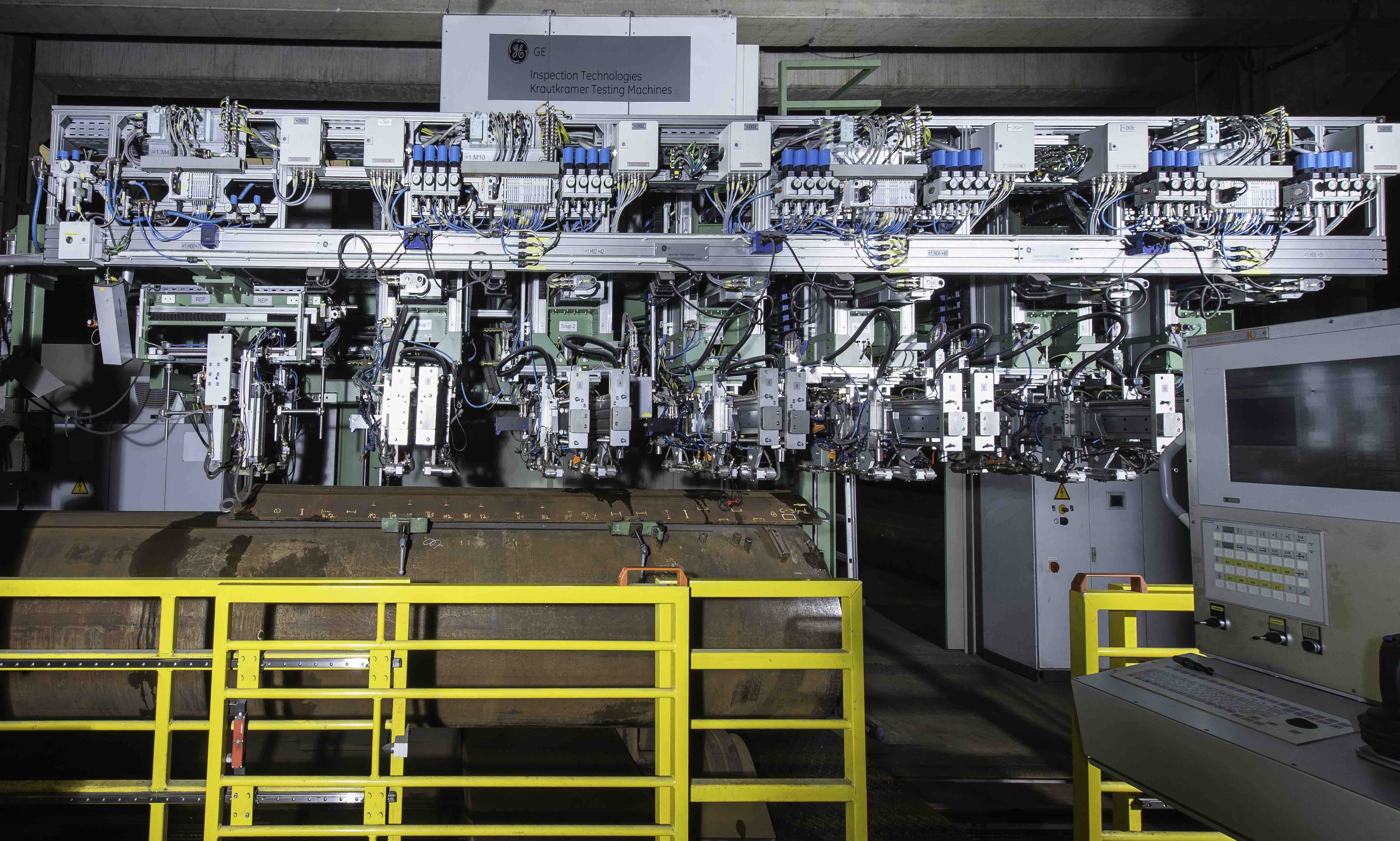
The General Electric testing machine (SNUP in German) was delivered and installed at EBK in 2011. It tests SAW-welded pipes made with carbon steel of various grades. Typical dimension ranges are 12- to 100-inch diameters, with 5- to 80-mm wall thicknesses and up to 80-foot lengths.
The newer, phased-array systems provide a high level of flexibility and speed, and can be designed for demanding production environments. Depending on the scope of the test, a SNUP can perform an automated test on a pipe in three to five minutes, based on industry standards (Shell DEP, DNV-OS-F101).
The testing machine consists of a lifting frame, test-tracking mechanics, water circulation system with an automatic filter, laser system for automatic weld bead tracking, PLC control unit, UT-phased array instrument design and GE proprietary UT-software.
The robust test-tracking mechanics minimize vibration to ensure stable and repeatable results. The mechanics are equipped with specific rotation point for a better weld following, particularly for smaller diameter pipes.
Manufacturing of CLAD pipes represents a new challenge for UT testing. As a result of the formation of columnar crystals after welding, the layer in the weld bead area is difficult to test with ultrasonic sound. Standard test techniques and conventional equipment lack sufficient UT instrument performance and the necessary flexibility to adequately test CLAD. The standard GE SNUP machine design, combined with GE phased-array UT electronics and software, was flexible enough to fulfill these new requirements with only minor adaptions.
Approach, Experience
Among the advantages of phased-array technology is its ability to use multiple elements to steer, focus and scan beams (sector scan) with a single-transducer arrangement. Moreover, the technology can create “virtual probes” which are individually programmed and configured.
With one physical probe, several virtual probes can be created. For each virtual probe, a separate set of parameters can be adjusted in the software. This allows for a flexible system for all possible bevel preparations to test for lack of fusions, as well as combined testing of inner and outer defects, by adjusting the angle of incidence for each specific virtual probe, which represents a single shot.
GE standard-phased array probes for SAW testing can steer the angle of incidence between -10° and 85° due to the integrated wedge and the small pitch. The housing of these probe types is identical to standard conventional probes.
Another advantage of the phased-array approach is the ability to check the coupling through the back wall instead of using sound transmission through the weld, which keeps the attenuation variation in a narrow range. In some cases, a variation of only 6 dB is permitted. Furthermore, a sector scan is available for each virtual probe. The sector scan is used during the static calibration to identify the best phased-array settings for detecting specific reference flaws.
One classic misconception is that one phased-array probe replaces many conventional probes. However, due to the anisotropic nature of CLAD materials, depending on the specific geometry of the pipe and weld, certain test arrangements are no longer effective.
The combination of growing demand coupled with the increasingly corrosive quality of oil and gas has led to consistent growth in the CLAD market, despite fluctuations in oil and gas prices. It is a premium market for pipeline manufacturers with few suppliers who can overcome the significant engineering, manufacturing and quality-testing challenges.
Conclusion
There have been about 80 SNUPs delivered by GE (and its German predecessor, Krautkramer, prior to the GE takeover) worldwide since 1999. The average lifespan of a SNUP is about 15 years, with some systems being used for over 20 years.
The machines need to be reliable: When a pipeline manufacturer wins a project, their manufacturing kicks into high gear. It is not uncommon for a manufacturer to run at full capacity for six days a week. The correct implementation of technology enables oil and gas pipeline owners to stay ahead of costly and dangerous failures.
Authors: Jochem Beissel is plant manager for Eisenbau Krämer – Kreuztal in Kreuztal, Germany. He holds degrees in mechanical engineering and welding engineering from the University of Cologne, University of Aachen and GSI SLV, Germany. His Ph.D. focus was in welding techniques for producing longitudinal-welded CLAD pipes.
Frank Kahmann is global principal engineer GE Ultrasonic Testing Systems and works with GE customers while providing guidance to external partners and other GE divisions. He holds a Ph.D. in physics from the University of Osnabrueck, Germany.
Jeffrey Stetson is product manager for GE Ultrasonic Testing Systems for automated ultrasonic testing systems used to inspect pipe during manufacturing for the upstream and midstream. He holds degrees in mechanical engineering from The Pennsylvania State University and in applied physics from Shippensburg University of Pennsylvania.
Daniel Norton is in commercial operations at GE Ultrasonic Testing Systems and is responsible for developing the initial requirement to a concrete blueprint for the project execution and use of the system. He holds a bachelor’s degree in engineering from Carleton University, Ottawa and a master’s degree in science from Aachen University of Applied Sciences, Germany in mechanical engineering.
Jörg Ininger is a team leader at GE Ultrasonic Testing Systems, where he heads engineers working on welded pipes, aviation, rail and plate-testing systems responsible for both proposal management and project execution. He holds a degree in electrical engineering from Leipzig University of Applied Sciences.

Comments