
March 2016, Vol. 243, No. 3
Features
Improving Pipeline Corrosion Protection Systems with Computer Simulation
Computer-modeling technology has developed over a number of years and is now widely used to verify the performance of cathodic protection (CP) systems used in combination with coatings to manage the corrosion risk to underground assets.
Modeling can be used to verify the protection provided by the CP system and optimize its design. For retrofit designs, modeling can be used to firstly gain a quantitative understanding of the state of the structures, the remaining life of existing anodes and estimated date at which loss of protection will occur. Modeling can also be used as part of the integrity management of underground assets by correlating the survey data with the model.
This has the benefit that predictions can be based on the actual degradation rates of the coatings and other structural changes. Updated model predictions can be used to plan any remedial activities required, thereby providing a more accurate understanding of the condition of the asset and its future protection levels than that based on the design assumptions.
For underground assets such as pipelines, buried tanks and other structures, interference can significantly affect the performance of CP systems designed to protect structures from corrosion. There are many forms of interference that the CP engineer has to consider and mitigate, if the design is to perform as required over the life of the structure.
For example, anode interference can significantly degrade the ability of the anodes to supply the required current, interference can occur between structures protected by CP systems and external electrical sources (AC/DC) can also cause interference.
Predicting the possibility of stray current interference at the design stage, prior to physical construction, provides clear advantages. However, at the time when a system is commissioned, it is still possible that a problem is identified, with a requirement that the root cause then be identified.
Models can be used to assist with such investigative work, and help avoid implementation of short-term, reactive, solutions that do not address the complete situation. Reacting to immediate problems is a dangerous and potentially costly strategy, as stray current problems and corrosion build slowly over time.
Computational models simulate the physics of galvanic corrosion and the features of a CP system. The model simulates the electrode kinetics on the metallic surfaces, the coating barrier, the electrolyte (soil/concrete/water) resistivity, the internal resistance paths in the structures and the 3D geometry of the metallic structures in the electrolyte. In the case of interference, it may be appropriate to incorporate in the model the location and properties of adjacent power lines or railways.
The time required to build a model depends upon the complexity of the asset structures, but if electronic CAD/GIS data is available describing the structures and pipelines, the time can be significantly reduced.
The starting point for building a model is the location and properties of the pipelines, geometry of other structures to be protected by the CP system. All the metallic surfaces are defined, including the type of material they are constructed from and the coatings applied to the surfaces. Where it’s appropriate, insulating surfaces can also be incorporated.
The polarization properties of the different metals used in the structure and the soil resistivity are selected based on the materials and the environment where the assets are located. It is important to select appropriate polarization data for the electrolyte (soil) characteristics at the location.
While the focus of this article is the use of modeling to protect onshore assets, modeling is also used in other applications to support CP design decisions and to predict and mitigate corrosion risk, for example, for offshore pipelines, oil and gas structures, ships and other marine facilities. Recent research yielded modeling technology able to predict the corrosion risk to aircraft structures and land vehicles, such as automobiles.
A recent interesting case study involved the design of protection systems for buried pipelines in an oil and gas station. The buried pipelines are generally electrically connected with other underground metal structures in stations, such as grounding systems made of bare metal, which affect the current distribution and protection effects.
It is difficult to give full consideration to these effects in a traditional design approach as the equations used to assess the protection provided by the anode ground beds do not consider such complex interactions. Computer simulation provides a useful tool to predict the CP current and potential distribution, and to optimize the design of CP-anode groundbeds in such cases.
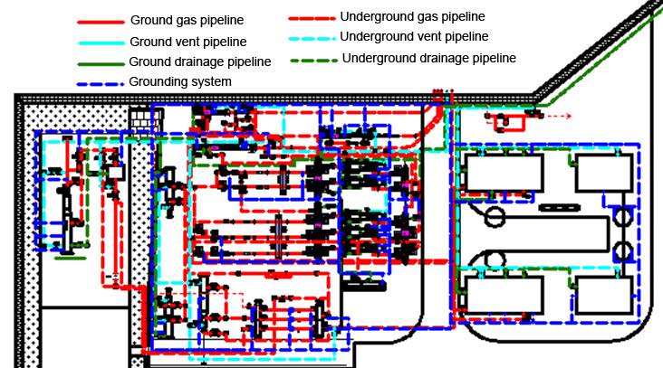
In the case study, the computer simulation was used to optimize the design of the CP-anode groundbeds. Beneath the oil and gas station a high-resistivity layer was identified, so distributed shallow anode groundbeds were chosen for the CP design. The key for the success of the CP design is how to distribute the shallow anode groundbeds to get satisfactory CP effect. Figure 1 shows the distribution of metal structures in this station.
The underground metal structures include gas pipelines, vent pipelines, drainage pipelines and grounding systems, which are electrically connected together. Asphalt and cold wrap are major coatings for buried pipelines and the grounding systems are composed of hot dip galvanized flat iron material. The average soil resistivity down to a depth of 2 meters (m) was about 30Ω·m.
Based on the geometry and distribution of the buried metal structures in the station, a 3-D model was established, including all the electrically connected buried metal structures and the surrounding soil zone.
The polarization characteristics of different buried metal structures were used as cathodic boundary conditions, which were obtained from laboratory polarization curve measurement in the soil sample taken from the actual station. The BEASY Corrosion & CP software was used to solve the mathematical model and obtain the potential distribution for different arrangements of the anode groundbeds. The 3D model and simulation meshes (Figure 2).


Scheme 1: When anode groundbeds were arranged at location 1, 2, 7 and 10 (Figure 3), the polarized potential distribution (Figure 2) of all underground pipelines in this station is given. Only the buried pipelines close to the anode groundbeds had the polarized potential more negative than -850mV (CSE), while the others were still under-protected. Therefore, new anode groundbeds should be added to improve protection effect.

Scheme 2: When anode groundbeds were arranged at location 1, 2, 3, 6, 7, 8, 10 and 12 (Figure 4), the polarized potential distribution of all underground pipelines was given. There still exist buried pipelines not meeting the CP criteria. The number and locations of anode groundbeds needed to be further optimized.

Scheme 3: When anode groundbeds were arranged at location from 1 to 12 (Figure 5), the polarized potential distribution of all underground pipelines was given. For Scheme 3, the polarized potentials of all buried pipelines in the station were between -850mV~ and -1200mV (CSE), which met the CP criteria.

By following this procedure it was possible to determine the CP design that met the CP criteria. Following the design study, the scheme was implemented and the predicted polarized potentials were compared with measured data (Table 1). The calculated results were in agreement with the measured data, and the largest relative error is less than 10%, except at two points (C1, C5), indicating that computer simulation is effective in predicting the protection provided by the CP system and optimizing the arrangement of the anode groundbeds in the station.
Having developed the model further, studies can be performed to evaluate the protection provided to the oil and gas station over its design life by simulating the degradation of the coatings and possible damage scenarios. In this way, the asset efficiency can be optimized and exposure to risk reduced.
Table 1: Comparison between calculated polarized potentials and measured data.
| Test point | Measured polarized potential(V, CSE) | Calculated polarized potential(V, CSE) | Relative error |
| C1 | -0.902 | -1.04 | 15% |
| C2 | -0.874 | -0.92 | 5% |
| C3 | -0.92 | -1.00 | 8% |
| C4 | -0.922 | -1.01 | 9% |
| C5 | -0.927 | -1.06 | 14% |
| C6 | -0.959 | -1.03 | 7% |
| C7 | -1.004 | -0.98 | 2% |
| C8 | -0.955 | -0.88 | 8% |
| C9 | -0.962 | -0.89 | 7% |
| C10 | -0.965 | -1.00 | 3% |
| C11 | -0.934 | -0.90 | 3% |
| C12 | -0.923 | -0.92 | 0% |
| C13 | -0.95 | -0.96 | 1% |
| C14 | -1.004 | -1.06 | 6% |
| C15 | -0.865 | -0.94 | 9% |
| C16 | -0.96 | -1.03 | 7% |
| C17 | -0.975 | -0.99 | 2% |
| C18 | -0.966 | -0.94 | 3% |
| C19 | -0.961 | -1.01 | 5% |
| C20 | -0.856 | -0.92 | 7% |
Summary
The design and operation of CP systems for underground assets is complex because there can be interactions that compromise protection and can shorten the life of the systems while overprotection can result in coating damage. In some cases, interference issues can be difficult to detect as they may only become significant later in the life of the structure.
Models can then be exploited to simulate the effect of alternative remedial actions. The effects can be complex, and (as configurations of structure and CP systems become more complex) difficult to predict by manual methods.
Finally, it is important to be able to predict and mitigate these phenomena as they can reduce the life of the CP system and increase the risk to the structural integrity, even when individual anode systems are well-designed.
Authors: Robert Adey is director of strategic development at C M BEASY Ltd. He has over 30 years of experience in the development and application of computer modeling software for corrosion and CP applications in the oil and gas, defense and aerospace industries. Adey earned a master’s of science and a doctorate degree from Southampton University, UK. He can be contacted at r.adey@beasy.com
Yanxia Du is an associate professor at the Corrosion and Protection Center, University of Science and Technology in Beijing, China. She can be contacted at duyanxia@ustb.edu.cn

Comments