
June 2012 Vol. 239 No. 6
Features
Bypass Method For Recip Compressor Capacity Control
This article considers the bypass method for capacity control in reciprocating compressors. The method is the oldest in controlling outlet capacity, which is used in all types of compressors for turndown capacity between 100% and zero.
The reciprocating compressor is a positive displacement machine. During normal operation, it takes in a quantity of gas from its suction line and compresses the gas as required to move it through its discharge line.
Unlike centrifugal compressors, reciprocating compressors cannot self-regulate their capacity against a given discharge pressure. In fact, it keeps compressing without limitation unless we specify the range of work, and that capacity will be a unique quantity at any point in time. Thus, we have a real need to control the capacity of the reciprocating compressor.
Moreover, in most instances, a reciprocating compressor needs to be unloaded by a bypass line for startup. Otherwise, if the compressor is started in full-load conditions, the driver’s required torque during startup will be 350% of nominal torque. By comparison, electrical motors are designed for 40-60% of starting torque capability. This is another reason for using a bypass line. (1,2)
Bypass Method
Capacity control by means of an overall bypass can be applied without limitations to all compressors; it provides the recycled gas entering the suction line close to the normal suction temperature. This arrangement is normally employed for starting and shutdown purposes. It covers zero to 100% range as well.
When capacity turndown is required, a bypass with a control valve is necessary. Depending on the system requirements, the bypass may only be across the first stage. More often, the bypass spills back across all stages unless the differential pressure is too high to be handled by a single control valve. Maximum allowable pressure drop through control valve shall be specified by the compressor manufacturer.
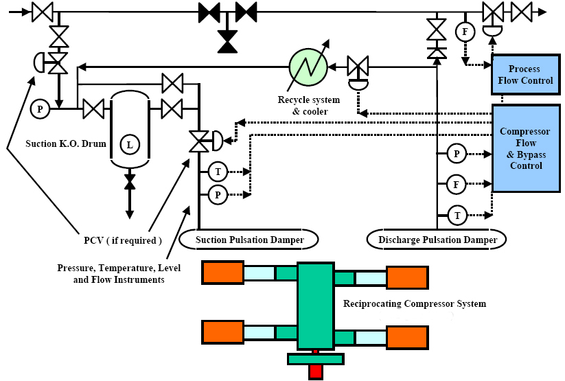
The take-off point for the bypass must be at the downstream of a heat exchanger so that cooled gas will be spilled back to the suction. If there is no exchanger in the discharge, the bypass must branch into the suction line upstream of an exchanger. As an alternative, a cooler may be placed in the bypass line. This means that an after-cooler or a bypass cooler may have to be used. In addition, a check valve in the discharge pipe is required to prevent the high-pressure gas from flowing back when the compressor is at standstill. In any case, the bypass should tie in upstream of a suction knockout drum so that any condensate resulting from the expansion cannot enter the compressor (Figure 1).
Bypass control is preferred compared to other methods because of its smoothness, simplicity, low initial costs, high practicality and ease of application. Because this regulation method is very uneconomical, it should only be used if the compressor has to be operated at reduced capacity for a short time or in combination with another energy-saving type of capacity control such as unloader valve, clearance pocket and step less method.
When a bypass is used in combination with step control, five-step operation is more efficient than three-step operation.
In multi-stage compressors, a bypass around the first stage or a partial bypass can be used. Bypassing the first stage only on multi-stage compressors reduces the energy wasted in the bypass method. It allows a reduction in delivery flow by a factor depending on the rated compression ratio of the first stage.
However, it should be noted that there is a restriction on rate of flow which is to recycled in the first stage. This restriction is related to maximum allowable discharge temperature, which should not exceed 150 degrees C (300 degrees F) for all operating and for hydrogen service and services with molar mass of less than or equal to 12, should not exceed 135 degrees C (275 degrees F).
(Actually, in fixing the regulation range of a first-stage bypass, it must be remembered that a reduction of the flow to the second stage causes a drop of all inter-stage pressures, and consequently it can lead to excessively high pressure ratios and discharge temperatures in the following stages. Moreover, these pressure shifts can cause overload in the last stage. The recycled flow has to be restricted by means of an orifice plate in the end of bypass pipe.)
Therefore, a logic based on this principle should regulate the output of all stages simultaneously. Otherwise, the compression pressure ratio in the individual stages would change considerably, leading to an increase in the compressed gas temperature. (4)
The minimum capacity that can be attained depends on the number of compression stages. The more stages used for a given overall compression ratio, the wider the achievable control range. In many process applications, 50-60% of total flow rate is generally recycled in the first stage. If a lower turndown capacity is required with such a compressor, the problem can be solved by providing an additional bypassing line or compressor stage or cylinder.
As a principal rule each stage should be controlled with one bypass valve which is independent of other bypass valves. For 100% capacity turndown, in two-stage reciprocating compressors, maximum 60% of flow should be recycled in first bypass line and the residual 40% should be controlled by the second stage line; for three-stage compressors, the arrangement is the same as for two-stage compressors, but the second recycle line is between the third and first stage outlet point.
In this arrangement, the suction and the discharge side of second stage should be controlled by an additional bypass line or a differential pressure controller (PDT). Because of lower initial cost and more reliability during operation, the PDT method is preferred and designers use it in new modern plants. PDT device prevents overpressurizing of the second stage cylinders during needed turn down capacity and protects cylinder outlet gas temperature.
For four-stage compressor, first and last stages are controlled by two separate recycled lines and two PDT devices used for protection of second and third stages. This arrangement can be developed for compressors with more stages, however, with more PDT controllers, compressor logic control is complicated and it should be analyzed by the manufacturer.
If side stream flow is available in the process designation of multi-stage compressors, e.g. between stage three and four in five-stage compressors, the better solution is dividing flow in two full turndowns between upstream and downstream of the side stream inlet point. Thus, total inlet flow (100% capacity) to first stage is controlled between first and third stage; moreover, side-stream flow is separately controlled by two last stages (i.e. fourth and fifth stages).
Actually, a compressor can operate in all turn down capacity from 100 to zero using partial bypass line and PDT device in several stages. The major difference with overall bypass method is the rate of waste energy, which is reduced by machine because it can significantly run at a lower energy level and save power in this condition. In other words, discharge pressure in each stage is decreased as long as pressure ratio and discharge temperature in next stage are in allowable range.
This matter is very important and critical for last stage because all modifications and process values have been changed in upstream of last stage. Thus, in order to keep discharge pressure unchanged in the last stage, discharge temperature may be increased to out of standard recommendation, causing major defect on machine elements. As was discussed previously, the best solution is lower pressure ratio or additional stages in compressor construction. (5)
With reduction of discharge pressure in each stage, the absolute power input can be reduced while the compressor flow rate (Q) is increased, respectively. This matter is important for control valve sizing so that they can operate in variable operating conditions such as turn down.
If the compressor should run a long time (longer than 24 hours) in zero turn down, it is better that discharge pressure (or pressure ratio in last stage) is reduced by control valve in the relevant bypass line. However, it should be noted that there is a restriction in low-pressure ratios in compressor construction. Especially, some components such as outlet valves, cylinder O-rings and crosshead pin bearing may be destroyed in low-pressure ratio conditions. In this way, cross head bearing lubrication is a major problem, which should be taken into consideration in all cases of operation. (6)
Startup With Bypass Control Valves
In the following, we investigate the capacity control procedure of a reciprocating compressor with bypass valves in three stages. As mentioned previously, the first and third stages are controlled with separate bypass control valves and second stage is protected by PDT device. Note that all control valve set points are adjusted together and finalized during the compressor-commissioning period. However, the manufacturer has already defined PDT set points during FAT (factory acceptance test). Moreover, designers mention relevant settings in instrument set point list document.
Figure 2 is an illustration of a capacity control diagram. In the figure, PCV, PT and PDT are pressure control valve, pressure transmitter and differential pressure transmitter respectively. The main objective of the capacity control is to maintain constant suction pressure (PT1). The capacity of the compressor is controlled by bypass over the first stage (PCV1) and bypass over the second and third stage (PCV2) and pressure differential controller on second stage (PDT1).

Figure 2: Schematic of control devices.
If compressor suction pressure PT1 is decreased, the first stage bypass valve (PCV1) could be opened continuously up to a percent of stroke (between 50-60%) until the pressure differential in the second stage (PDT1) is below the set point which is the maximum allowable differential pressure.
If suction pressure (PT1) continues falling, the controller will open the second bypass line to the first stage by valve PCV2. This bypass valve will open continuously up to 100%. Now, the first stage bypass (PCV1) will be able to control main suction pressure (PT1) with PCV2 in parallel. Thus, desired pressure is obtained by high-pressure gas, which is recycled through first, second and third stage bypass valves.
When both valves are fully open, the compressor will operate in full recycle mode until suction pressure is increasing again. When suction pressure is increasing, the bypasses will close in reverse. Rapid valve movement causes rapid load change on the compressor. To prevent this from happening, the control valve’s characteristic should be linear and the stroke travel rate should be approximately two minutes. However, this rate can be adjusted during compressor commissioning.
Authors:

Ali Ghanbariannaeeni is a rotating equipment specialist with NARGAN Engineers and Constructors, Tehran, Iran and can be reached at A.Ghanbarian@ nargan.com, www. nargan.com.

Ghazalehsadat Ghazanfarihashemi is a rotating equipment specialist with Sazeh Consultants Engineers, Tehran and can be reached at Gh.Ghazanfari@sazeh.co.ir, www. Sazeh.com.

Comments