
March 2012, Vol. 239 No. 3
Features
Protecting A Centrifugal Compressor From Surge
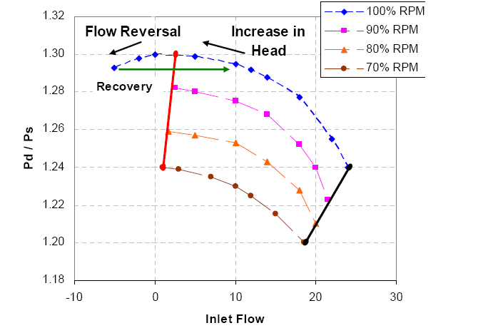
Surge is defined as the operating point at which centrifugal compressor peak head capability and minimum flow limits are reached. Actually, the working principle of a centrifugal compressor is increasing the kinetic energy of the fluid with a rotating impeller. The fluid is then slowed down in a volume called the plenum, where the kinetic energy is converted into potential energy in form of a pressure rise.
When the plenum pressure behind the compressor is higher than the compressor outlet pressure, the fluid tends to reverse or even flow back in the compressor. As a consequence, the plenum pressure will decrease, inlet pressure will increase and the flow reverses again. This phenomenon, called surge, repeats and occurs in cycles with frequencies varying from 1 to 2 Hz. So, the compressor loses the ability to maintain the peak head when surge occurs and the entire system becomes unstable. A collection of surge points during varying compressor speed or varying inlet gas angle is fitted as surge line. In normal conditions, the compressor operates in the right side of the surge line. However, during startup/emergency shutdown, the operating point will move towards the surge line because flow is reduced. If conditions are such that the operating point approaches the surge line, flow recirculation occurs in the impeller and diffuser (Figure 1). The flow separation will eventually cause a decrease in the discharge pressure, and flow from suction to discharge will resume. Surging can cause the compressor to overheat to the point at which the maximum allowable temperature of the unit is exceeded. Also, surging can cause damage to the thrust bearing due to the rotor shifting back and forth from the active to the inactive side. This is defined as the surge cycle of the compressor.
Anti-Surge Control Systems
These systems detect when a process compression stage is approaching to surge and subsequently take action to reverse the movement of the operating point towards the surge line (SL). This decreases the plenum pressure and increases the flow through the compressor, resulting in stable working conditions. It is normally achieved by opening a control valve in a recycle line (Anti-Surge Control Valve or ASCV), returning the discharge gas to the inlet of the compressor via a suction cooler. The resulting increase in compressor inlet volume flow moves the operating point away from surge.
Due to inaccuracies in measurements and response times of transmitters and valves, Anti-surge control achieves a surge control line (SCL) parallel to the surge limit line. The control line is offset to the right of the surge line by a margin; typically equal to 3- 10% of inlet volume flow at surge (Figure 2). However, a lower margin is also desirable because higher efficiency could be obtained by closing the recycle valve.
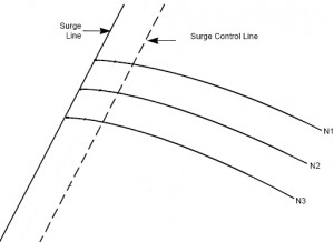
Figure 2: Surge Protection Definitions.
In real operation, compressor performance curves in the coordinate system are unique for constant given suction conditions. This means that the variation of inlet conditions leads to changing compressor performance curves. On the other hand, since inlet temperature decreases, inlet molecular weight increases or inlet pressure increases, the differential pressure across measuring device would go up for the same inlet capacity. So for the purposes of control, new coordinate system is used which must be invariant (or independent) to changes in inlet conditions. Therefore, the effects of inlet temperature, gas molecular weight and compressibility factor are not required to be considered in the controlling system. In this regard, several invariant coordinates are obtained by compressor manufacturer. They use dimensional analysis for the generation of these invariant systems (or compressor map). The two most important systems are:
1) Compressor polytropic head (or differential pressure) versus square of flow rate in suction and
2) Pressure ratio versus square of flow rate in suction.
Flow through the compressor suction is equivalent to the pressure drop in orifice or venturi installed at the inlet or outlet of compressor. Thus, pressure loss in orifice or venturi can be calibrated as a function of compressor flow rate.
A compressor map is illustrated by superimposing both performance and system resistance curves independent of rotational speed (Figure 3). For compressors with inlet guide vanes, compressor map is represented by a new family of curves that do not depend on suction conditions either. This additional coordinate could be a function of either guide vane position or equivalent rotational speed.

Figure 3: Compressor map.
Anti-Surge Controller System And Algorithms
Proportional–integral (PI) and proportional–integral–derivative (PID) are two major control algorithms which are used to control imperfectly known compression systems. The basic procedure of these algorithms is that the controller output should be a function of the difference (Error, e) between two values which should be controlled (process variable, PV) and its set point (SP) (Figure 4).
When operating in the stable region at the right-hand side of the SP-line, where the error, e, is positive, the controller output is forced to be zero and integrators should be reset to avoid wind-up. As the flow decreases due to a disturbance, PV decreases as well and — at a certain point — where PV< SP, the error, e, becomes negative. Here, the controller comes into action opening the anti-surge valve. This action pushes the PV back to the stable region at the right-hand side of the SP-line. Moreover, small disturbances should not lead to big reactions. But a fast and resolute opening of the valve is required when the control line is exceeded in the direction of the surge limit. Therefore, the controller has a nonlinear gain behavior when the controller deviation (PV-SP) is negative.  Figure 4: Compressor controller schematic. Earlier matter about nonlinear gain controller leads to considering derivation term in logic control of system. Actually, effect of the derivative (D-action) term is that it often allows the control response to be accelerated without increasing the risk of instability, because it is a measure how fast the system is responding and action will tend to counter the oscillatory action. However, it will also make the system more sensitive to signal noise. Thus, the simpler PI algorithm is sometimes more useful than full PID control. But it (PI) is limited in speed of its response and is unable to take the machine out of surge in the event that the operating point crosses the surge line. In other words, the D-action should be incorporated by changing the set point due to a change in flow (dF/dt). When the flow decreases rapidly (dF/dt << 0), the danger of going to surge exists in compressor. Therefore, the original set point (SP) is increased with a higher margin. As a consequence, the PV-line passes the SP-line earlier. The controller will react earlier and have a higher output, resulting in an increased control effort. It is should be noted that for the smaller PV/SP, D-action is more important because, it will cause a higher value of the weighing factor of this margin. So, the effect of the D-action due to a decrease in flow is the increase in set point, resulting in a negative error earlier than without the D-action. Logic controller without derivation and with just the proportional plus-integral control system is adequate for many changes in plant operating conditions. For activation of this method, second control line is located between the proportional plus-integral control and surge lines. When this control line is crossed, there is a step increase in the output from the controller that causes the recycle valve to open. This kind of valve opening is called valve jumping (Figure 5).
  Figure 5: PI algorithm with step line. The controller output decays exponentially with time to a point where the proportional plus-integral control system resumes control. Moreover, the momentary valve position calculated by the PI algorithm is overridden by an adjustable additive component. Anti-Surge Input Requirements
As earlier mentioned, flow rate is the main data obtained from suction or discharge. Moreover, pressure and temperature in suction and discharge are needed to establish the operating point on the compressor performance curve. Recommendations for the minimum input requirements for a given system arrangement can be found in Figure 6.

Figure 6: Compressor Surge Control System Layout.
Additionally, it should be noted that a molecular weight change of 50% or a variation of 10 or more is considered a significant change in the mixture gas composition. In such conditions, compressor map and relevant surge line is individually generated for each gas component and the magnitude and direction of each is compared with the other. Obviously, the finalized surge line shall cover and include all unstable regions, obtained by the performance maps.
The response time of a transmitter for the measurement of a process variable used by the surge control algorithm should be less than 100 milliseconds. Moreover, the emergency shutdown situation will require the fastest response time from the control system. The shutdown operation does not affect the surge control algorithm because the sole function of the controller under the shutdown operation is to fully open the control valve as quickly as possible. In such condition, the recycle control valves should be able to move from fully closed to fully open in less than 2.0 seconds.
Anti-Surge System layout
Figure 6 is an illustration of the Anti-Surge System layout. On centrifugal discharge, a check valve shall be installed to prevent reverse flow and minimize surge. The check valve shall be located as close as possible downstream of the compressor to minimize mass inventory. In other words, a check valve at the compressor outlet will limit the downstream volume and increase the required system response time of the surge control system. In parallel operations, compressor units should have check valves installed to assure effective surge control of each compressor.
In order to protect the compressor adequately from surge, the discharged flow must be restored very quickly. For this reason the anti-surge recycle connection and anti-surge control valve shall be located upstream of the check valve as close as practical to the compressor discharge connection. Moreover, a cooler in the recycle line may have to be considered, to suitably control the suction temperature and thereby prevent the compressor from going into surge. The line-up and tie-in point of the recycle line on the suction side of the compressor shall be at the upstream of the suction scrubber in order to prevent liquid from entering the compressor.
If the compressor bypass control line is taken downstream of the discharge cooler (called “cold bypass line”), an additional hot gas bypass line upstream of the discharge check valve is required to protect the compressor against surge during start-up, trip and normal operation (Figure 7).
In “hot bypass lines,” the suction cooler is installed after the recycle line, which is taken directly from the discharge and recycled to the upstream of the suction cooler.

Figure 7: Hot and Cold Recycle Valves.
Recycle lines and their components shall be sized to handle compressor flow rates under rated conditions and all other specified operating and start / stop conditions.
Anti-Surge Valve Specification
The anti-surge valve (ASV) is a fail open solenoid valve. This means that it needs a high signal of 20 mA to close the valve, and a low signal of 4 mA to open the valve. When a failure occurs, the valve will usually receive a low signal and it will open, which is the safe position.
In startup and normal stop, the compressor will initially operate with the valve at 100% open. The valve characteristic for 100% open should be sufficiently removed from the compressor operational region, during compressor startup. ASV should be sized for 1.8 to 2.2 times of maximum surge point flow rate. Oversized valves will not provide the sensitivity required for particular operational settings and will restrict the performance of the compressor; actually, the valve characteristic lines will become too far from the right of the operation.
Operational flexibility should be considered so that one compressor unit could be isolated from the other units at a station, while two or more compressors are running as parallel or series. Moreover, this may require independent bypass loops and quick closing of valves at the suction side of each compressor. Quick closing of valves will prevent overloading the other units if one compressor is shutdown.
Therefore, to provide maximum protection and operating flexibility, it is recommended that surge protection systems with their own dedicated recycle loops should be provided for each process compression stage.
Authors:
Ali Ghanbariannaeeni is a rotating equipment specialist with NARGAN Engineers and Constructors, Tehran, Iran. Ph: 9821-8891-4926-30. Email: A.Ghanbarian@ nargan.com, www. nargan.com.
Ghazalehsadat Ghazanfarihashemi is a rotating equipment specialist with Sazeh Consultants Engineers, Tehran, Iran. Ph: 9821-8873-9924. Email: Gh.Ghazanfari@ sazeh.Co.ir, www. sazeh.com.

Comments