
September 2018, Vol. 245, No. 9
Features
Progressing Cavity Pumps Prove Cost-Effective for Multiphase
By Robert Kurz, Manager Business Field Oil & Gas, Netzsch
Increasing production of heavy oil, extra heavy oil, and bitumen is critical to a stable world economy. These crudes generally require special production techniques to overcome their high viscosity.
While many in the industry have focused on such methods as steam assisted gravity drain (SAGD), cyclic steam injection (CSI) and vapor recovery, flow assurance solutions are also of vital importance.
These well streams are a combination of crude oil, water, gas and sand; the proportions of each vary by region and reservoir. There are distinct economic, environmental, and facilities management advantages to transferring the complete well stream to gathering and processing facilities rather than separating the components at the well site.
To make this transfer, the pump system selected must be reliable, safe, and capable of handling the variations in fluid composition and process conditions.
Positive displacement pumps, especially theac progressing cavity pump (PCP) are a good choice for multiphase fluid transfer for crude oils with high viscosity. The PCP is a cost effective solution compared to other conventional oilfield in-field pumping alternatives.
Stimulating Reservoirs
In recent years, many have tried to increase production rates by using new techniques to stimulate reservoirs. Most of these methods require flow assurances and surface transport techniques.

Selecting pumps to transport multiphase fluids, consisting of oil, water, gas, and formation solids (sand), is critically important. Multiphase fluids in traditional field developments will typically free flow to gathering stations, through surface lines pushed by the natural formation pressure.
However, heavy oil and extra heavy oil pose particular challenges for flow through pipelines because the increased viscosities result in high friction losses.
Figure 1 shows a typical production model for multiphase flow. The flow assurance aspect is critical for carefully managing production rates. Flow line resistance can have a strong influence on the production rates. For heavy oil regions, it becomes a key factor in deciding the specific production philosophy.
A simple way to use a multiphase pump is installation at the well head to simply boost the well flow to gathering and processing stations. In this case, multiphase pumping is quite simply a way to add energy to the unprocessed well fluids, which enables the liquid/gas mixture to be transported over long distances without the need for prior separation.
There are typically two in-field separation operating scenarios options – conventional separation either close to or at the well site, or use of a multiphase pump. Separation close to the well site is not always possible, and may require significant infrastructure and investment.
|
Item |
Conventional separation |
Multiphase pump |
|
List of process equipment |
2-phase product separator 2-phase vertical surge vessel Crude oil transfer pump Export LP compressor LP compressor suction scrubber LP compressor after-cooler |
Multiphase pump Pump control system Optional seal oil & seal system |
|
List of utilities package |
Instrument air packages (air compressor/dryer/receiver) Diesel generator |
Instrument air packages (air compressor/dryer/receiver) Diesel generator |
|
Environmental concern/s |
Continuous venting/flaring from LP product separator, positive crankcase ventilation (PCV) Amount of gas venting/flaring is significant during compressor shutdown. |
No concerns – gas handled in closed system with no venting |
|
Operability consideration |
Require frequent monitoring |
Usually unmanned |
|
Footprint |
>100 m² |
Can be as little 20 m² |
Table 1: Comparison of conventional separation with multiphase pump.
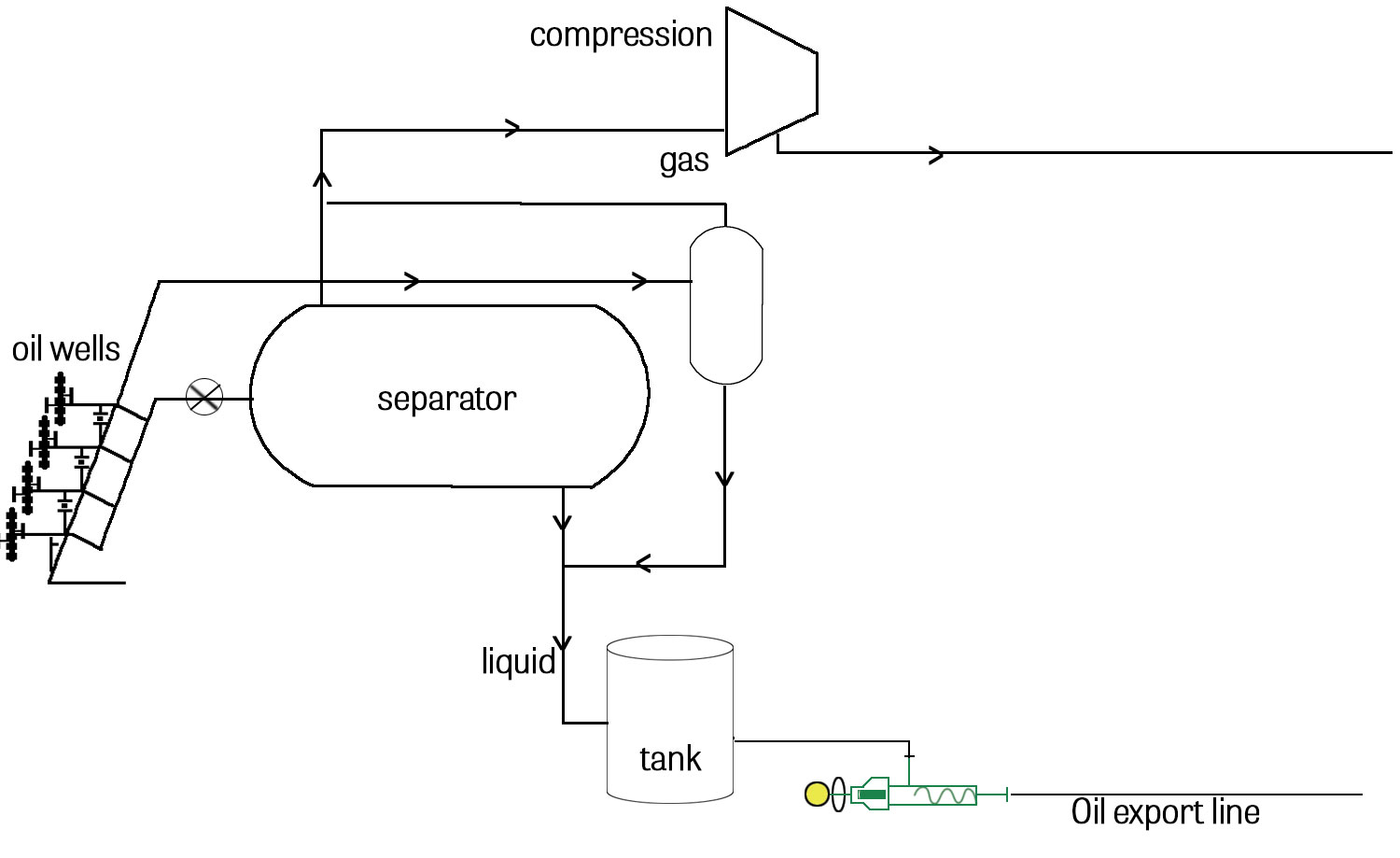
This increases facility investment costs due to the complexity of the extreme environmental conditions, for example, cold temperatures, in which heavy oil fields are often located. Figure 2 shows a diagram of conventional separation equipment.
The information suggests that multiphase pumping may be the simpler choice from an equipment perspective. From an environmental point of view, using an enclosed system to handle gas with little or no need for gas venting to the atmosphere is the more desirable option.
Pumps located at the well head or on pump pads must handle changing process conditions, due to the variations in formation and well behavior. This is especially an issue for the many multiphase pumps deployed in depleting fields, which have a tendency to demonstrate unstable cycling behavior characterized by an active production period followed by an inactive period. In addition, the unprocessed multiphase oil streams may have entrained (free gas) fractions as high as the high-nineties.
The pump equipment is already coping with challenging conditions, so when sporadic slugging is thrown into the equation, it can affect the pump. The slugging can result in gas flow only for periods lasting from 15 minutes to several hours. The pump must be able to cope with such variations. During gas slugging periods, it is likely that some liquid will be carried with the gas as a liquid or a vapor.
The worst case scenario for a pump is long duration of dry gas flows, which is tantamount to dry running of the pump. These technical design and control challenges must be overcome to ensure equipment is reliable and efficient when placed into service.
Installation Challenges
While there are many benefits to installing multiphase pumps, there are also a variety of challenges posed by process and environmental conditions. The following conditions must be addressed in any successful multiphase pump package:
- Well shut-in pressure is often high, more than 20 bar. Pump suction side design is for the shut-in pressure, as well as the normal running pressure, which is typically much lower
- Varying inlet pressures lead to varied required displacement volumes, so the pump must have a variable speed drive that can vary the flow rate
- The pump must be able to tolerate periods of gas slugging
- Installation is nearly always outside, so the pump must be able to handle extreme heat and cold
Integration Philosophy
Good system integration is required to overcome process challenges, including prolonged slugging. More than in any other PC pump application, the system needs to be orientated to work with the pumps to ensure pumps are not damaged during such times.
The dry run protection device embedded in the stator can detect a frictional heat buildup due to lack of lubrication from the pumped fluid. The control system can react by starting a lubrication pump. In the simplest form, the dry run protection can just trip the pump until the temperature reduces. System complexity will vary based on geographical location.
Another example is a simple liquid collection tube and recycling line arrangement, which has been widely used in Russian oilfields. It is usually applied with a recycle line flow controlled by a manually set throttle valve. The leakage collection device is sized to give a buffer of fluid to allow a reasonable operating period during typical slug flow durations.
Environmental Considerations
Pump equipment must be protected from harsh environmental conditions, especially extreme cold temperatures.
The pump stator is made of an elastomer; effective pump operations depend upon flexible elastomeric properties. As the temperature goes lower, elastomeric properties reduce and the tear strength reduces. As they approach the glass transition point, pieces of the stator material can become mechanically overworked and shear off.
Elastomer recipes can be adjusted to increase the rebound rate and change the effect of low temperatures. Alternative stator material recipes have been successfully and reliably applied in extremely cold Russian oilfields.
Mechanical Seals
Mechanical seal selection is less critical than might be expected. It is essential that “O” ring material is selected based on the expected temperatures, especially when operating in exceptionally cold temperatures. Seal selection depends on the gas fraction and the expected risk that the field could operate in slugging conditions.
For low gas fractions (less than 60%), using single mechanical seals with either no quench (API Plan 02) or a simple quench (Plan 62) has proved successful. Where gas fractions are higher, the use of higher integrity solutions can be considered, for example, a double mechanical seal and systems.
The simpler the solution, the more reliable it is likely to be. Even for higher gas fractions, the use of tandem seals with simple atmospheric buffer fluid tanks is very effective and avoids the need for more expensive and complex double seal and plan 53 systems.
It is also important to carefully select the buffer or barrier fluid. Use of 75/25 glycol/water solutions and diesel has been successful, with upgrades to fluids like isopropyl alcohol (isopropanol) or methanol.
PCPs are forgiving to mechanical seals, because the shaft speeds are very low and stuffing box pressure is the same as the suction pressure. Only one shaft seal is required, unlike twin-screw pumps with four shaft seals.
Robust Solution
PCP equipment can be easily tailored to meet the demands of multiphase oilfield locations. Elastomer selection is essential to deal with cold conditions, and use of package process and control solutions is especially critical. A PCP is simple to control; temperature increases are easily detected and the pump responds well and quickly to control adjustments.
The fluid handling qualities are extremely useful for handling low or very high viscosities. The PCP can also handle gas fractions as high as 99%, and can tolerate slugging conditions even without requiring control systems. P&GJ

Comments