
April 2022, Vol. 249, No. 4
Features
Application of Pipeline Cleaning Robot in Liquefied Natural Gas Pipelines
By Tai Yuan Chang, Assistant Chief Engineer, and Chuan Tse Hsiang, Assistant Chief Engineer, CTCI Corporation, and Fa Shian Chang, Professor of Electronic Engineering, Cheng Shiu University
Pipelines used to provide gas for the production of LNG use many butt-jointed valves. Similarly, when welding the valves, debris for grinding and welding spatter slag and dust will remain inside the pipes. Traditionally, pipes have been cleaned with in-pipe blowing technology, but that has been problematic because the method removes only 60% of the debris.
Much of the debris will still accumulate in the depressions, causing valve wear and leakage, which increases subsequent maintenance costs and reduces project quality. Therefore, it is necessary to develop new technologies to overcome such problems.
The in-pipe cleaning technology proposed in this article involves the development of a robot that cleans and absorbs residues. Test results show that the robot has over 95% cleaning ability and can travel in horizontal, vertical and curved pipelines that have diameters of 10 to 14 inches and a wall thickness of S100. The robot is reliable and easy to operate, improving project quality and safety.
Robot Development
The system architecture is divided into four parts:
The robot body includes a moving mechanism, an imaging mechanism and a cleaning mechanism. The imaging mechanism has an omnidirectional imaging lens, while the cleaning mechanism is a combination of a brush, a high-pressure blowing, and a suction device.
In addition, the sensing mechanism consists of a gradient meter and a meter wheel, and a control system using a logic controller (PLC), a human machine interface, a a display mechanism, a joystick, and an input/output unit.
Finally, the transmission unit comprises the instrument cable and a cord winder.
The following is an overall description of specifications and performance:
- Robot body
- The double carriage of the platform is 31 inches (80 cm) (length) by 8 inches (20 cm) (width) by 8 inches (20 cm) (height).
- Empty weight: 31 pounds (14 kilograms)
- Load capacity: up to 55 pounds (25 kilograms)

- Moving Ability
- Direct current (DC), brushless, motor-driven and controlled by proportional–integral–derivative (PID) differential mode.
- Underwired remote-control mode – the wired remote-control range can reach 164 feet (50 meters).
- Movement speed is over 0.6 miles per hour (15 meters per minute) and continuous variable speed.
- It can climb up to 90° and move 20 feet (6 meters) in a vertical pipeline
- The power wheel is capable of expanding and collapsing, and it can provide various adhesions.
- Rubber wheel by design and is capable of moving forward and backward.

- Cleaning Ability
- Suction ability: Can remove 0.2 ounces (5 grams) of particles with a particle size of 0.12 inch (3 mm).
- Blowing ability: Can act in the direction of gravity.
- Comes with brush head.
- Imaging Ability
With a remote monitoring image, the resolution is more than 960H with a 30fps frame rate. Transmissible image data can be stored in the built-in hard disk of the console, with a USB port for download.
- Applicable pipe diameter and other specifications
- Compatible with 10 to 14-inch pipelines (14 inches need to use double sections).
- Ingress protection level: IP32
- Vibration resistance (horizontal/vertical): 10 kg to 2 m/s
Experiment Testing
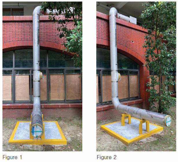
A simulation field must be as similar to the pipeline at the construction site as possible. CTCI Corporation provided one test skid, located at Cheng Shiu University. The size specification of the test skid is 14 feet (4.3 meters) (length) x 7 feet (2 meters) (width) x 13 feet (4 meters) (height) (Figures 1 and 2).
The purpose of the experiment was to provide the development team with a suitable verification platform. The prototype machine was tested repeatedly on this test skid. Through multiple tests and corrections, a prototype pipeline cleaning robot was produced that could move in the actual pipeline.
Site Testing
Once we completed laboratory development and achieved over 95% test success rate, we put it to test at construction sites to see whether the prototype pipeline cleaning robot could operate normally in the real environment. The following are test results at two worksites.
Case 1
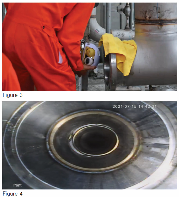
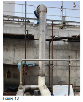
The test was carried out at a construction site in Kaohsiung City, Taiwan (Figure 3). The test scenario used a 39-foot (12-meter) pipeline with horizontal (Figure 4), vertical and elbow sections. During the test, we successfully overcame the challenge of turning and the problem of gravity support during vertical crawling.
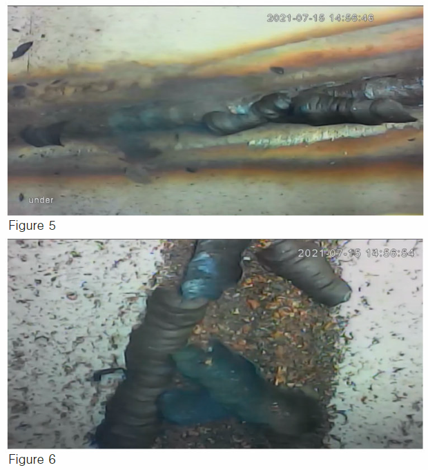
A clear picture showing the inside of the pipeline was sent back in real time (Figures 5 and 6), allowing engineers to see how clean the interior was. Cleaning functions, such as blowing, suction and sweeping, also worked normally. Finally, internal welding slag of the pipeline was successfully removed (Figure 7).
Case 2
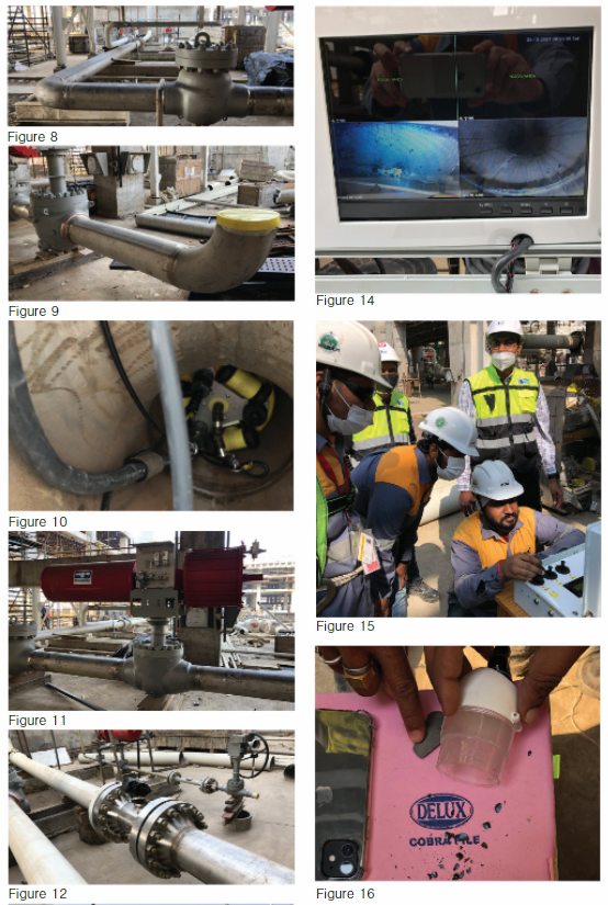
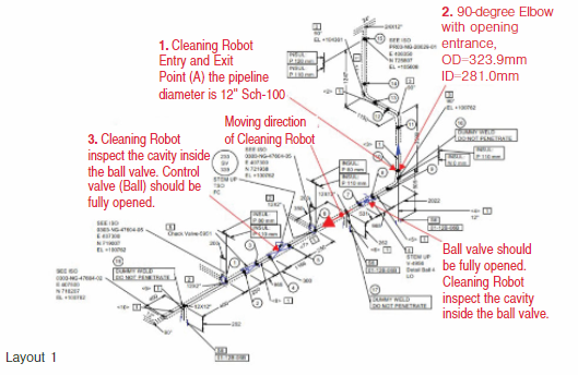
In December 2021, a submerged combustion vaporizer (SCV) outlet pipeline at an LNG regasification construction site in India was chosen for inspection using a pipeline robot (Figure 8). The inspection details are as follows:
- The pipeline diameter is 12-inch Sch-100.
- The inspection scenario of the cleaning robot started from a 90-degree elbow (Figure 9) and through the opening entrance (Figure 10).
- The robot moved horizontally through a control valve (ball valve) (Figure 11), magnetic flow transmitter (Figure 12), etc.
- Then it climbed vertically to the top (Figure 13).

In total, 82 feet (25 meters) of pipeline were inspected. Again, the cleaning robot successfully passed the challenge of turning and moved vertically to overcome the reverse force from the robot’s own weight and cable weight.
During inspection, a clear interior image of the pipeline was transmitted and displayed in real time on the screen of the control box (Figure 14). The engineers can use the real-time image to see the conditions inside the pipeline (Figure 15) before applying cleaning functions of blowing, suction and sweeping to remove the slag or debris located inside the ball valve cavity and on the weld joint’s inner wall. The cleaning functions worked normally as expected (Figure 16).
Conclusion
Having been tested at two construction sites, the pipeline cleaning robot has proven it can operate normally in the real environment and achieve the goals set. At present, we have only developed cleaning robots suitable for 10 to 14 inches of pipe diameters, but cleaning robots suitable for larger-diameter pipes will be developed in the future to improve pipeline cleanliness.
In addition, the modules can be replaced according to the needs of the project, such as the use of robotic arms, high-pressure nozzles and testing equipment.
Pipelines require reliable cleaning because they can impact the normal operation of valves, i.e., affecting the control and shut-off mechanism of the overall process fluid. When an internal leakage happens, it is necessary to repair and re-test, which affects overall completion time and related expenses.
By developing this industrial pipeline internal cleaning technology, we expect to improve the internal cleanliness of pipelines, reduce the chance of valve body leakage by 50% and cut consumption of other testing gases, such as nitrogen and low-temperature natural gas.
During operation, pipeline cleaning robots can improve the service life and reliability of valves and other accessories, such as instruments and pumps, providing owners with a safer and more economical operating environment.

Comments