
March 2021, Vol. 248, No. 3
Features
Inhibitor Development for Extreme Conditions in Deepwater
By Nihal U. Obeyesekere and Jonathan J. Wylde, Clariant Oil Services
Deepwater exploration and production has seen a higher-than-average growth in the past 10 to 15 years when compared to other sectors in the industry, brought about by high and stable production and technological advances that have driven lifting costs down to all-time lows.
Chemical innovation has been required to keep up with the trends of “deeper, hotter, higher,” all with an overriding need to develop more environmentally benign solutions. Certainly, these challenges exist in the chemistry of corrosion inhibition where solutions must perform under more and more hostile conditions.
It is challenging to develop chemicals for the combination of arctic conditions, extremely hot and high-pressure systems,1,2 high sour systems and ultra-deepwater applications where chemicals are deployed via umbilical tubes to remote subsea wells.
In this paper we will discuss corrosion inhibitor development for ultra-deepwater systems that experience most of these extreme conditions, including downhole temperatures as high as 400 degrees F (204 degrees C) and pressures as high as 20,000 psi (1,379 bar).
To develop new inhibitor products for such harsh environments, more than 100 new corrosion inhibitor blends were formulated and tested during this study. Active corrosion inhibitor bases were blended with solvents to yield 35% to 40% activity.
As an initial screening test, the products that were unstable and phase separated when exposed to 400 degrees F for 48 hours were rejected. The remaining products were screened using a combination of techniques to qualify for subsea high-temperature applications:
- Performance testing using a rotating cylinder electrode (RCE), a rotating cage autoclave (RCA) and jet impingent
- Umbilical deployability evaluation (particle size distribution, 14-day capillary stability loop test, nonvolatile residual [NVR] testing and high-pressure, low-temperature viscosity, etc.)
- Secondary inhibitor properties (flash point, oil/water partitioning, pour point, etc.)
- Material compatibility (metals, elastomers, thermoplastics)
- Ecotoxicity3,4
After screening numerous blends, two chemicals were selected and were commercialized. Here we refer to them as Chemical A and Chemical B. Both are water-soluble and oil-dispersible products that are stable to 400 degrees F for more than 48 hours.
Chemical B was formulated with environmental impact at the forefront and, wherever possible, raw materials that were benign were used. Typical components used included polymers (bis-, dimer, trimer and polyquats etc.), alkoxylated amines and imidazoline, low toxic amines (C6 or C8) and sulfiding agents.
One of the most important aspects, beyond corrosion inhibitor performance, is the evaluation of deployability through umbilical tubes. Testing must mimic the tortuous path experienced by a chemical on its journey from manufacturing vessel to subsea wellhead. This process is guided by two standards5,6 that provide a high-level overview of recommended practices.
However, it is the opinion of these authors that the document lacks guidance on how to execute these guiding principles, which leads to some ambiguity and nuances in the testing performed from laboratory to laboratory.
The specific choice of tests is a balance between the minimum required data set and the risk appetite/operating philosophy of the ultimate end-user (i.e., operating company). The high-level standards are interpreted by the end-users who will then decide the appropriate test method based on company (or sometimes even personal) experience.
One of the most important properties (sometimes overlooked) is particle size distribution. The number and size of particles in a liquid can be measured using light scattering or microscopic methods. One recognized method is SAE AS 4059,7 which evaluates and describes particle distribution in a liquid.
In addition to particle distribution, other complementary stability tests can be deployed, such as the U-tube manometer method, rotary evaporator method and NVR testing. As the root cause of failure in an umbilical tube is caused by the exposure of the chemical to the temperature and pressure conditions in each system, these methods can give a clear image of chemical behavior under system conditions.
Another challenge specific to umbilical deployment is the formation of a vacuum in the tube. If the wellbore pressure (and the “crack” pressure of the injection valve) is less than the hydrostatic pressure (caused by the column of chemical in the injection line), then the chemical will flow into the wellbore until the pressure is equalized.
This leads to a vacuum in the capillary and the formation of vapors that are more corrosive than the native chemical. This further leads to the formation of higher viscosity residues caused by solvent loss. These residues can be more corrosive and/or may gunk the line.
Both chemicals selected for this project underwent the aforementioned testing procedures and were found to be free of gunking and were not hydrate foaming.8-10
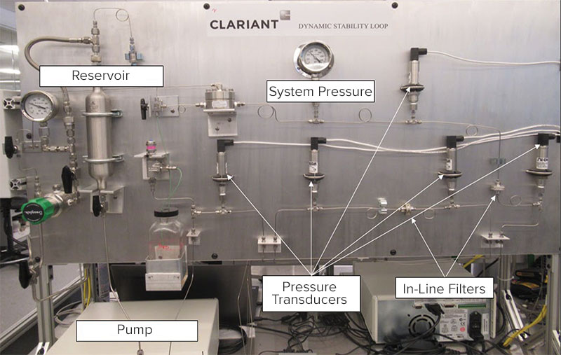
The final “acid test” for umbilical deployment is to flow the chemical through a simulated umbilical flow loop. The dynamic capillary test was performed on a customer-built, high-pressure flow loop that continuously monitors differential pressure at four locations in the flow path (cold capillary, hot capillary, cold filter and hot filter) and can be seen in Figure 1.
Corrosion inhibitor performance testing is performed to evaluate the ability of the chemical to effectively control corrosion. The correct combination of tests can mimic precisely the conditions experienced throughout the system and provide a proper assessment of integrity to properly design facilities for the life of the field.
Screening Tests – Rotating Cylinder Electrode Tests
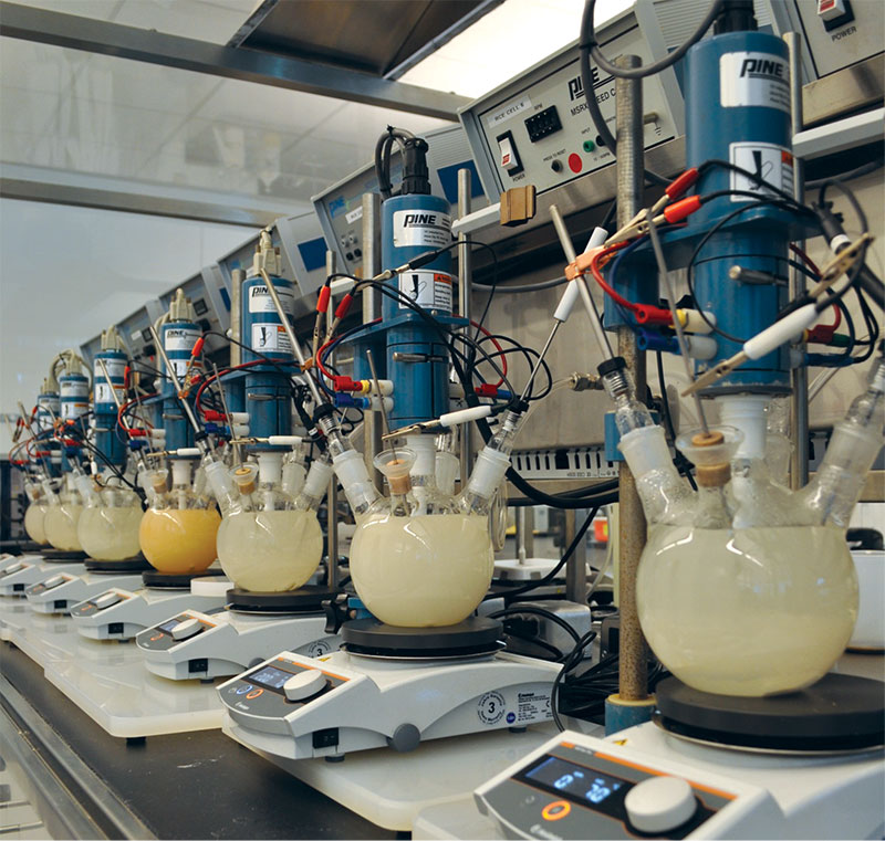
Initially, RCE tests were used to screen all chemical blends. The tests were conducted in Pyrex glass reaction kettles continuously purged with test gas at 194 degrees F (90 degrees C) (highest practical temperature for this low-pressure test). The electrode rotation rate was set at 2,000 rpm, which generated a wall shear stress of 7 Pa. Linear polarization resistance (LPR) was used to measure electrochemical characteristics of the testing system. After the baseline corrosion rate was monitored for 1½ hours, 50 ppm (based on brine) of corrosion inhibitor was added. The electrochemical information was recorded during the testing and data were compiled and calculated after the testing. The experimental setup for the RCE tests is shown in Figure 2.
RCA and jet impingement tests ensure the products perform in a variety of flow conditions; both low- and high-shear conditions were emphasized to test the product performances in different flow regimes. The lower shear (up to 40 Pa) tests were performed using 0.26-gallon (1-liter) RCAs; higher shear tests were performed on a jet impingement device capable of producing an intermittent-shear stress up to 1,500 Pa.
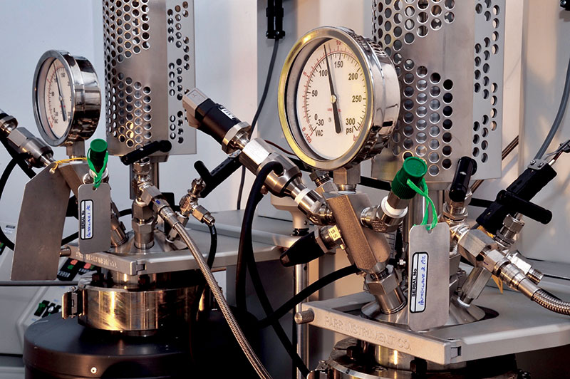
In RCA testing, three weight loss coupons fixed on the rotating cage were used in each autoclave. The coupon shafts rotated at 1,000 rpm, which corresponded to a 40-Pa shear stress.
The autoclaves were run at 392 degrees F (200 degrees C) and the partial pressures of gas matched to those experienced in the field. General corrosion rates were calculated by weight loss measurement. The autoclave setup is shown in Figure 3. The post-tested coupon surfaces were analyzed for pitting corrosion by using a high-powered microscope.
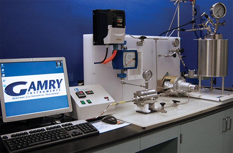
Jet impingement testing was performed at maximum shear stress (1,500 Pa) to determine the best performing products. A photograph of the jet impingement loop used in this study can be seen in Figure 4.
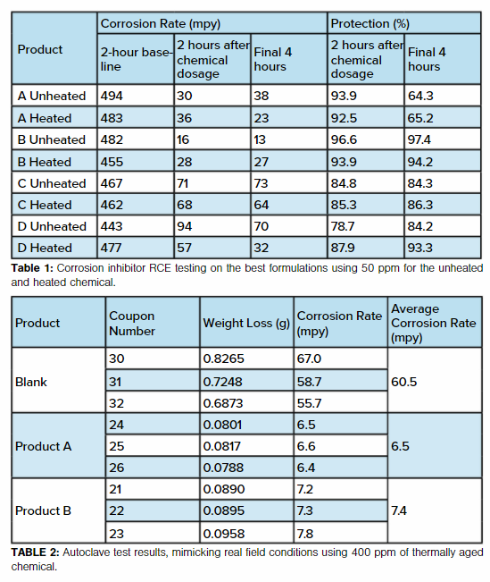
The best four thermally stable corrosion inhibitors screened in RCE tests at 50 ppm are presented in Table 1. This test distinguishes robust corrosion inhibitors and selects the best candidates for further and more detailed performance evaluation. Results show that unheated Product B provided the quickest corrosion rate drop from its baseline in the first two hours after addition of chemical and finally achieved 97.4% inhibition. The heated Product B performed similarly and provided 94.2% corrosion inhibition.
Product A and Product B were tested in the RCA and using jet impingement tests. Only the thermally aged chemical was tested (400° C for 48 hours). For RCA testing, the results are shown in Table 2.
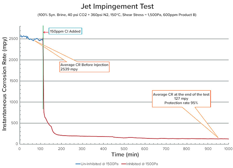
The coupons were analyzed using a high-powered microscope, and no pits were observed on the surfaces of the coupons from the treated tests. Jet impingement testing of Product B at a shear stress of 1,500 Pa is shown in Figure 5.
There was an average baseline corrosion rate of 2,539 mpy and a corrosion rate of 127 mpy at the end of the test at a dose rate of 600 ppm. The product performed well with a protection rate of >95%.
Inhibitor performance can be increased with the increase of the dose rate in the jet test; the test established the extreme film persistency of Chemical B even under the most intense conditions of shear possible.
Conclusions
Product B is a carefully formulated, environmentally compliant corrosion inhibitor selected out of more than 100 experimental blends. After extensive performance testing work, it has shown excellent thermal stability at static and dynamic conditions under high-temperature (>400 degrees F) and high-pressure conditions.
This water-soluble corrosion inhibitor product was stable to 400 degrees F for more than two months. It has showed outstanding corrosion inhibition within varied flow regimes under low- and high-shear stress in autoclave and jet impingement tests. It also satisfied all deep-water testing criteria applicable for chemical transport via umbilical under extreme conditions.
When tested alongside Product A (non-environmentally compliant), it is possible to fulfill intense performance criteria with environmentally compliant chemistry.
The value of such testing programs is in the determination of a risk management strategy for assets during the design phase. When one has a high degree of confidence and trust in the laboratory-to-field correlation of the suite of test methods, one can afford to be bolder in the design envelope of decision making.
At the same time, this means that the integrity of the infrastructure is not compromised, failure of which can lead to environmental and fiscal catastrophe.
References:
Obeyeskere, A. Naraghi, L. Chen, S. Zhou and S. Wang, “Novel Corrosion Inhibitors for High Temperature Applications,” CORROSION 2005, Paper No. 05636 (Houston, TX: NACE, 2005).
L.A. Skogsberg, B. P. Miglin, “Establishment of Corrosion Inhibitor Performance in Deepwater Conditions,” CORROSION 2001, Paper No. 01005 (Houston, TX: NACE, 2001).
N. Obeyesekere, A. Naraghi, L. Chen, S. Zhou, D. Abayarathna, “Synthesis and Evaluation of Biopolymers as Low Toxicity Corrosion Inhibitors for North Sea Oil Fields,” CORROSION 2001, Paper No. 01049 (Houston, TX: NACE, 2004).
Obeyesekere, A. Naraghi, R. Prasad, H. Harry Montgomerie, “Environmentally Friendly Corrosion Inhibitors for CO2 Corrosion,” CORRORION 2000, Paper No. 00020 (Houston, TX: NACE, 2000).
API 17TR5, “Avoidance of Blockages in Sub-Sea Production Control and Chemical Injection Systems,” Blockage Avoidance in Subsea Injection and Control Systems (BASICS) Joint Industry Project (JIP) (Washington, DC: American Petroleum Institute [API]).
API 17TR6, “Attributes of Production Chemicals in Subsea Production Systems,” Blockage Avoidance in Subsea Injection and Control Systems (BASICS) Joint Industry Project (JIP) (Washington, DC: American Petroleum Institute [API]).
“Guide to Contamination Standards,” www.parker.com/Literature/EMHFF/ConMon/Guide%20to%20Contamination%20Standards.pdf
J.R.L. Smith, A. U. Smart, M. V. Twigg, “The Reaction of Amine. Polyamine and Amino Alcohol Corrosion Inhibitors in Water at High Temperature,” J. Chem. Perkin Trans. 2 (1992): pp. 939-947.
M.A. Quraishi, “Tailoring and Synthesis of Corrosion Inhibitors,” CORRROSION 2004, Paper No. 04400 (New Orleans, LA: NACE, 2004).
K.A. Esaklul, A. L. Ballard, “Challenges in the Design of Corrosion and Erosion Monitoring for Deepwater Subsea Equipment – Stretching the Limits of Technology,” CORROSION 2007, Paper No. 07338 (Nashville, TN: NACE, 2007).

Comments