
July 2021, Vol. 248, No. 7
Features
Options for Internal Inspection of Difficult-to-Check Pipelines
By Michael Beller and Carlos Enrique Sabido Ponce, ROSEN Group
(Editor’s note: This is the second of a two-part article. Part 1 appeared in the June issue of P&GJ.)
In the second part of this article, different case studies introduce the different categories of tools for the inspection of challenging pipelines, including specialty free-swimming, umbilical and robotic.
Our first case study highlights the specialty free-swimming category of tools. Each case study will describe the full solution to the inspection challenge at hand.
Of course, the inspection tool is an essential element in completing these inspections, but the complete solution encompasses an extensive list of other components, including in-field work, pre-inspection cleaning procedures and much more.
The asset to be inspected was an offshore, 36-inch (914-mm), 280-mile (450-km) pipeline that runs from a platform to an onshore gas terminal.
Although the pipeline had been inspected using inline inspection (ILI) technologies, changes in operating conditions and the addition of a hot-tap tee (HTT) to the system made the inspection task a unique, industry-first challenge. The inspection solution had to overcome the following:
n Ultra-low flow of gas at inlet, approximately 0.11 mile per hour (mph) (0.05 meter per second [m/s])
n Presence of a 1,650-pound (750-kilogram), nonreturn clapper valve
n High side flow where the gas enters the pipeline with a speed of 34 mph (15 m/s) through the HTT
n High-speed and heavy wall thickness downstream of the HTT
The overall approach to the inspection solution was to provide a ruggedized magnetic flux leakage (MFL) tool and a cleaning tool that could perform in the low- and high-flow pipeline sections, as well as traverse the check valve and the flow on the HTT side.
The engineers designed customized pulling units for the MFL tool and the cleaning/gauging tool, which decreased gas bypass to an absolute minimum.
Because of the challenging nature of the inspection, the tool designs had sufficient contingency. A safety factor of 8 was used to ensure the MFL tool could provide enough drive force to push open the check valve. The tools could perform at speeds as low as 0.22 mph (0.01 m/s).
Before taking any solution into the field, a comprehensive testing program was performed to confirm the tool design.
The cleaning and gauging tool brought out little debris, and there was no significant damage to the gauge plate or the tool body. Therefore, the MFL tool was launched and arrived at the receiver after 60 hours.
For the first 1.2 miles (2 km), the tool had an average speed of approximately 0.2 mph (~0.1 m/s), but then the velocity rose sharply at the HTT. After passing the tee, the velocity steadily increased as the pressure along the pipeline decreased.

Export flows and the pressure at the terminal were used to identify boundaries to model operating conditions. These were plotted against modeled calculated values to monitor performance.
A dashboard was developed to show the pig progress and the estimated arrival times at key points in the system. The performance of the model was excellent, and the predicted tool arrival times were in line with the run in the field.
Free-swimming benefits – This case study highlights a view of the unique advantages of a specialty free-swimming solution, starting with the range of the inspection. The total distance to be inspected was 280 miles (450 km). In combination with the low-pressure operating conditions, the ILI took 60 hours.
Only the specialty free-swimming category of tools for inspecting challenging pipelines would be able to travel that distance without a supplemented energy source like a cable. In addition, this solution could be used during operation, although the operational parameters were complex.
Case 2: Umbilical-Operated – The Back and Forth of Getting the Data
This case study highlights a scenario in which the benefits of an umbilical-operated solution were truly able to shine, in a situation in which, perhaps, the other categories could not have provided similar advantages. In this case, various challenges made this pipeline difficult to inspect, but it was not truly unpiggable.
Large oil producers have extensive terminals for offshore production, where product moves from platforms to onshore crude oil storage terminals through pipelines. Arriving onshore, product is temporarily stored in tanks.

Once the product fills the tanks, the crude oil is transported back onto the ocean to massive ships. Every step of the way, the integrity of the infrastructure the product passes through is of utmost importance. For an offshore operator in West Africa, this was no exception. Having previously inspected one of the pipelines and encountering significant corrosion, the integrity of the 42-inch (1,067-mm) export line became a concern.
When constructed, this 42-inch line was designed to be piggable and fitted with an onshore launcher and a subsea receiver. However, the receiver was not in operation, reversing the direction of the flow was not possible, and the pipeline was deemed difficult to inspect.
The need for a one-way entry approach became clear, with access to the pipe from onshore. KTN AS (a company of the ROSEN Group) provided an ultrasound (UT) umbilical inspection approach. The umbilical not only acts as a fail-safe mechanism, but it also provides much-needed power to the tool train.
The solution also mitigates the need for product flow. In addition, a live data feed is transmitted to tool operators onshore who can monitor the inspection progress and the tool’s positioning in the pipeline. The umbilical tool passed through all bends along this complex pipeline route.
The inspection tool was launched through the onshore flange. At 1.55 miles (2.5 km) per 12-hour shift (just over 200 mph [89 m/s]), the tool crawled into and back out of the pipe. The tool traveled about 4.85 miles (7.8 km) offshore toward the loading buoy, covering enough distance to perform an integrity assessment on the rest of the pipeline.
After the return inspection had been completed, the focus turned to the first 1,640 feet (500 meters) after the launch site. The complex routing of the pipeline allowed the tool to rotate, ensuring that the 480 sensors on the sensor ring would inspect the complete inner pipe wall.
Although UT has many upsides, especially for corrosion detection and sizing, one clear downside is the sensitivity of the sensors to debris. Because this specific pipeline was challenging, no cleaning was conducted prior to the inspection.
However, because the crawler traveled into and out of the pipe, data were recorded in both directions, increasing the probability of achieving full sensor coverage in the debris-covered sections of the inner pipe wall.
For facilities like this, one must run a tight schedule to meet production demands; a vital part of operations is ensuring the safety of all assets. This umbilical crawler approach provides a no-compromise solution for collecting the data needed to understand the integrity status of an asset, without interrupting valuable production time.
Umbilical-operated benefits – In this case, the umbilical-operated tool provided a variety of benefits unique to this category, the first being coverage. The nature of the solution traveling into and out of the pipe resulted in the assurance that full pipeline coverage could be achieved. In addition, to ensure inspection success, the cable provided real-time inspection data to on-site tool operators.
Finally, the biggest benefit in this case was the ability to focus the inspection tool on one previously defined critical section of the pipeline. Having the umbilical operation made it possible to focus on the first 1,640 feet of the pipeline.
This umbilical solution allowed for a more focused inspection on a pre-defined critical section of pipeline.
Case 3: Robotic, Self-Propelled Solution for Offshore Vent Line Inspection
Some assets were never meant to be inspected internally. This case study shows the application of the robotic tool category for challenging pipelines.
Offshore subsea vent lines are a crucial part of processing systems. However, they were not designed to be inspected internally, nor had a successful ILI of vent lines ever taken place. However, ROSEN’s Challenging Pipeline Diagnostics division performed an ILI on the previously unpiggable 10-inch (254-mm) subsea vent line.
After obtaining a comprehensive overview of the asset, the following challenges were identified:
- No conventional access for ILI tools
- Pipeline accessible only from main platform
- No or very low flow and pressure
- No previous inspection knowledge
Cleanliness unknown
After reviewing the limitations, it was determined that the solutions would need to be based on low-friction technology, have bidirectional and self-propulsion capabilities, and be able to cope with moderate amounts of debris.
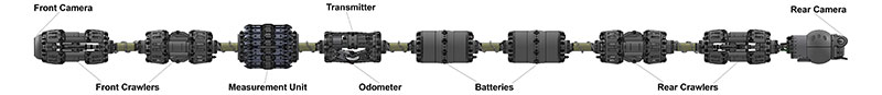
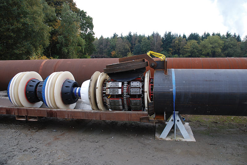
A sophisticated 10-inch robotic propulsion unit was developed. The solution included specialized cam driving components that provide an increase in pull-force capabilities, allowing for the utilization of high-resolution MFL technologies. The design contained both vertical and horizontal bidirectional movement capabilities and distance tracking.
To validate the solution’s capability to negotiate the proposed vent lines, the inspection conditions were replicated on ROSEN’s testing grounds in Lingen, Germany, with the construction of a test tower and loop.
The structure consisted of a vertical riser containing a pipeline exceeding 66 feet (20 meters) in height, with a 3-D bend situated at the bottom of the pipe to transition the pipe from vertical to horizontal. The horizontal section consisted of one 3-D bend with two straight pipe connections. The self-propelled robotic propulsion unit successfully made its way through this test loop and crawled up the 66-foot vertical riser unassisted.
After extensive testing and tool configuration, the robotic propulsion unit was cleared for the inspection of the subsea vent lines. On the riser, a transition spool was replaced with a 2.5D (pipe diameter) elbow to create an entry point that transitioned the tool from horizontal to vertical. During the 29-hour operational shutdown, an ex-safe atmosphere in the pipeline needed to be established. This was achieved by introducing nitrogen into the pipeline.
During the inspection, the robotic propulsion unit functioned properly and maneuvered in and out of the pipeline as expected, successfully negotiating the 2,116-foot (645-meter) section of pipe.
Throughout the inspection, all functional components and communication remained fully operational, and the data collected met all reporting requirements. This marked the first-ever successful ILI of a subsea vent line using an MFL-equipped robotic propulsion unit.
The optimized, high-resolution MFL measurement unit successfully detected and accurately measured internal and external pipeline anomalies, such as corrosion, girth weld features and mill defects.
This full integrity assessment enabled the operator to move forward with critical integrity management while securing the safety of the environment and platform worker, and managing public perception.
Robotic solution benefits – In this specific case, the benefit of the robotic solution was its ability to move vertically through this unique asset type.
The robotic propulsion unit enables the sensor technology to gather valuable data along the entire length of the pipe section by climbing its way through the pipeline.
The configuration of the robotic propulsion unit allowed for both vertical and horizontal bidirectional movement.
Conclusions
Today, there is a wide range of options to inspect difficult-to-inspect pipelines, formerly referred to as unpiggable. Different propulsion methodologies are available, from free-swimming to umbilical to ILI tools with their own crawler units.
Each of these technologies comes with its own specific strengths – but also drawbacks. It is important to understand these tool characteristics and realize that the different tool classes available today are not in competition with each other.
A vast range of inspection solutions is commercially available today, not only for traditional pipelines but also for those challenging pipelines that previously could not be inspected from the inside.

Comments