
April 2021, Vol. 248, No. 4
Features
Evaluation of Metal Loss Corrosion with RSTRENG
By Joe Pikas, Technical Toolboxes
Corrosion metal loss assessment is a method for evaluating the strength of corroded pipelines that includes criteria from ASME/ANSI B31G, which is a guide for the evaluation of the remaining strength of corroded pipe.
This method permits evaluation of large areas of metal loss in the body of the pipe and pitting clusters, and the effects of corrosion on other areas of the pipe. The original B31G and Modified B31G (Level 1) focus primarily on single pits found on the pipe.
However, RSTRENG (Level 2) focuses on multiple pits and clusters found on the pipe, whereas Battelle’s NG-18 work was used as a Level 1 evaluation for the more conservative B31G calculations.
Several assessment methods are in widespread usage in the pipeline industry for evaluating the remaining strength of line pipe affected by metal loss caused by external or internal corrosion. The primary methods are ASME B31G, the Modified B31G Method and the Effective Area Method, as in software products such as RSTRENG and API 579 Levels 1 and 2.
Even though this table is not comprehensive of all available methods to evaluate pipe affected by corrosion, it encompasses the calculations to evaluate corrosion affecting onshore pipelines according to the U.S. Department of Transportation (DOT) Regulations CFR 192 and 195. Several other assessment methods have been used, which include DNV RP-F101, PCORRC and CORLAS.
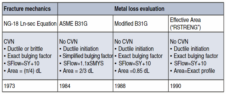
The development of the more common metal loss assessment methods, and technical attributes, are listed in Table 1.
In the late 1960s/early ’70s, the NG-18 equation was established. Because of the complexity of these equations and the industry just getting into personal computers, mainframe computers were used to generate a set of tables for the corrosion field personnel to assess metal loss corrosion.
About the same time, we had just run our first low-resolution pig run and had to assess anomalies. Our biggest challenge was not the assessment and the calculation but locating these anomalies in a mountainous area of Pennsylvania. Using permanent magnets for geo-references that were placed approximately every two miles, slippage occurred on the wheel counter(s) from the hills. In addition, being unfamiliar with the accuracy of the pig, we quickly learned to use the casings as references that filled in the geo-gap where there were no magnets.
Once the process of chainage from two different locations was established, verifying the correct joint of pipe, then locating the metal loss defects lead to the final process being established. Using the mainframe-generated tables was a great enhancement to assess maximum safe pressure, and we did not have any metal loss forms to follow since we were taking the measurements.
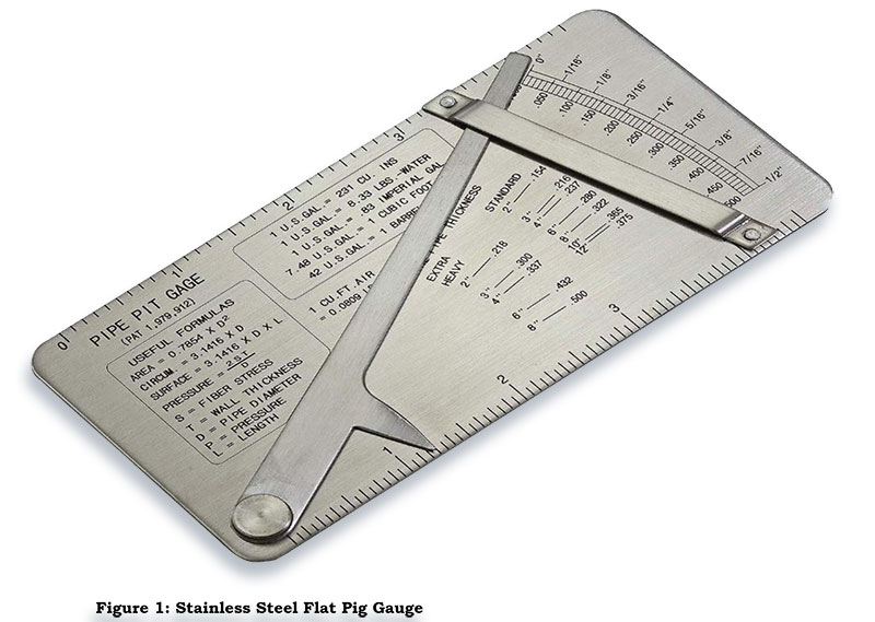
During the direct examination of the pipe, we created forms that are very close to those used today by using wax paper impressions, setting up 1-inch grids, and using a flat stainless steel (Thorpe) pit gauge (Figure 1).
A typical stainless-steel gauge that was used in the late 1960s for measurement is still used today. However, by today’s standards, this gauge should be used only for screening purposes due to inherit inaccuracy issues of plus/minus 10 mils (0.254 mm) and limited length for measuring longer metal loss defects.
In addition, the mainframe-generated tables were used to assess metal loss combined with interaction rule of thumb for 1-inch (25.4-mm) circumferentially and longitudinally measurements between each pitting cluster to determine if they interacted with each other.
At that time, the industry was going through a major learning curve with the promulgation of the DOT CFR 192 Gas Rule, and pipeline operators and industry organizations could make an impact in the direction of how to respond to these new challenges.
In 1984, ASME introduced the “B31G” Supplement to the B31 Code for Pressure Piping of which B31.4 and B31.8 are sections. The B31G “Original” Method (Level 1) contained look-up tables of acceptable length dimensions of corroded areas depending on the maximum measured depth and the dimensions of the pipe, along with optional calculations for the “safe operating pressure” considering the measured length and depth of the corroded area.
The B31G Method is very conservative. After many direct examinations and verifications were completed in the field from in-line inspection (ILI) runs and no documented failures of pipelines were found from these types of metal loss corrosion evaluations, it was time for improvement of the original calculation. In addition, there was a lot of anecdotal evidence that the conservatism in B31G caused unnecessary pipe repairs.
This led to the development of the Modified B31G Method in 1987. The original calculation of the Folias bulging factor was put back in the equations, and the flow stress was set at 85% depth having the same maximum length and depth as the actual defect. It is also referred to as the “0.85 dL Method” or “Modified B31.G.”
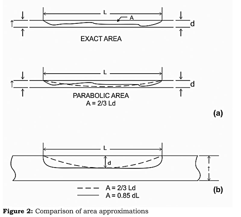
Figure 2(a) shows schematically how the 2/3 dL area approximation might compare to a realistic corrosion profile. Figure 2(b) compares the relative areas of the 2/3 dL approximation and the 0.85 dL approximation. The difference is small. The effect of this difference in the computed result compared to assessing the area more closely, such as how the Effective Area Method depends on the actual profile, is not consistent case to case.
The 85% area is less conservative than the parabolic profile as in B31G, which assumes the metal loss area is approximately two-thirds of the area of a uniform-depth defect but more accurate for longer-with-less-depth type of metal loss. The result of the changes of the approximate area, flow stress and the bulging factor is that the Modified B31G Method is typically less conservative than the original B31G in most cases. There are exceptions and they need to be recognized, noted and addressed.
Effective Area Method
As a further enhancement, the Effective Area Method was developed to assess for a truer profile of a longitudinal section through the actual corroded area by taking multiple and closer measurements along the profile of local metal loss of the surrounding metal.
The Effective Area Method and the Modified B31G Method were validated by 215 burst tests performed on pipe containing actual corrosion defects, service failures, pipeline hydrostatic test failures and artificial metal loss defects. During the hydrotest, the fittings to the pipe failed many times before the pipe wall burst. Many pipeline operators participated in these hydrotests to validate the equations.
The first commercially available computer program making use of the Effective Area Method was RSTRENG (for “remaining strength”), often referred to as “the RSTRENG Method.” Pipeline Research Council International (PRCI) set up an agreement with Technical Toolboxes to distribute the software and research documents that were involved in the development of this method including the testing results.
I was fortunate to participate in the testing of the RSTRENG software and in-house hydrostatic testing to verify the burst tests for PRCI. Transco, which is now part of Williams, was very involved in these types of activities and supported them through employee involvement regarding the development of this method. These activities promoted pipeline safety to the public and environment, as well as cost savings to their assets.
During the PRCI software testing, an error was found in the programing for RSTRENG1. The contractor had to correct the specific calculation that affected the results. After the bug was fixed, RSTRENG2 in Basic was immediately released for distribution. Remember this was pre-Windows, and we were still using DOS and dot matrix printers to make graphs.
Other Assessments
Level 1 is a formula that is essentially like the Modified B31G formula. It differs in the terms of the bulging factor, rewritten to cover the full range with a single equation, and with the remaining strength factor operating on the yield strength instead of a flow stress.
Level 2 is essentially the Effective Area Method, with the adjusted bulging factor. API 579 also recognizes a Level 3 analysis that relies on a finite element analysis. The Level 3 analysis is not related in any way to the methods discussed above.
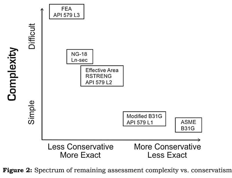
The methods discussed above present trade-offs for the user between technical rigor and accuracy on the one hand and ease of use and reduced accuracy on the other. In being modified from complex to simple, the exactness of the assessment decreases, but the simplifications were made to offset errors with increased conservatism.
Therefore, a less-conservative calculated result does not necessarily reduce safety, because in using the more exact method the user is making a better-quality assessment. The relative degrees to which the assessments differ in this regard are shown in Figure 2.
The pipe diameters tested ranged from 6-inch (152.4-mm) NPS to 48-inch (1,219.2-mm) outer diameter (OD), which encompasses the 36-inch (914.4-mm) OD of the line pipe used in APL. The wall thicknesses in the pipes tested ranged from 0.195 to 0.861 inch (4.953 to 21.869 mm), which encompasses the wall thickness dimensions of 90%+ of API standard pipe.
Conclusions
A technical basis for the most widely used assessment methods (ASME B31G, Modified B31G, and the RSTRENG-Effective Area Method) indicates that there are no limitations that prevent the successful application of these methods to pipelines built to industry standards.
The ability to apply these assessment methods is further provided by their many years of successful and reliable application to pipelines operating within their design limits.
Author: Joe Pikas has 54 years’ experience in pipeline construction, operations, corrosion, risk and integrity in the oil, gas, water and nuclear industries. He retired from a large gas company in 2002 and is still working with Technical Toolboxes as an engineering subject matter expert for their technical software applications. His consulting company is called Beyond Corrosion Consultants.

Comments