
February 2020, Vol. 247, No. 2
Features
Evolution of Ultrasonic Inline Inspection
By Herbert Willems, Thomas Meinzer and Gerhard Kopp, NDT Global, Stutensee, Germany
Inline inspection (ILI) by means of intelligent pigging has become a standard application to ensure the safe operation of pipelines worldwide. Ultrasonic inspection tools have proven successful for crack and metal loss inspections of liquid pipelines.
The progress regarding inspection tools over the last three decades is tightly connected to the progress of electronics and data processing during this time period. By timely implementation of the available state-of-the-art technology in the field of data recording, data processing and data storage, the performance of ILI tools has continuously improved.
An important aspect of these improvements is the measurement resolution resulting in the detection of smaller defects, as well as better sizing capabilities. Another instrument that is becoming more and more important for the proper design of ultrasonic ILI tools and their optimized application is ultrasonic modeling.
The progress of inline inspection tools is closely linked to the progress in electronics. Highly integrated electronic components allow for compact size and reduced power consumption at the same time. As a result, an increased number of sensor channels can be accommodated in less space, which is important for small-diameter tools. The corresponding improvements for the ILI tools are:
■ Increased sensor channels, providing better circumferential resolution
■ More parallel processing of receiving channels, enabling higher inspection speed
■ Less power consumption per channel, thus increasing inspection range
Data Digitization
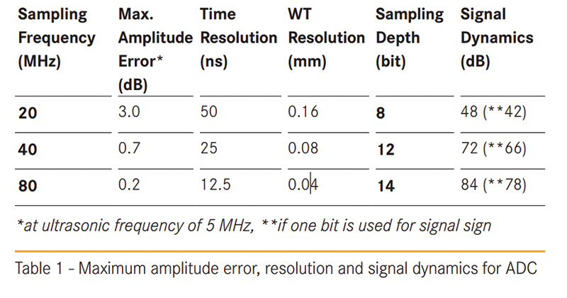
For ultrasonic ILI, ultrasonic sensors are used as transmitter and receiver (so-called pulse-echo technique). The received ultrasonic signals are transformed by the piezoelectric effect into electric signals, which are digitized and further processed. For the digitization of the ultrasonic signals, analog-to-digital converters (ADCs) are used. The ADC itself is a source of error depending on its sampling frequency and its digitization depth.
Using ADCs (e.g., 80-MHz sampling rate, 14-bit sampling depth), the amplitude error and the time error can be neglected for ultrasonic inspection frequencies of 5 MHz. Furthermore, the sampling depth of at least 14 bit provides a dynamic range adequate for the recording of ultrasonic signals. (Figure 1)
After digitization, the inspection data are processed using field-programmable gate arrays (FPGAs) in connection with microprocessors. From 1990 to 2010, the clock speed of the microprocessors has increased by a factor of about 100, while the progress in computer power as measured by the microprocessor transistor count has changed by a factor of 1,000 in the same period. These improvements applied in ILI allow for advanced onboard data processing not possible in the past. Examples of application include:
■ Less data reduction required since more data can be recorded
■ Dynamic adaptation to varying medium properties
■ Preprocessing of the inspection data to speed up the offline data analysis process
In the past, ILI had limited data storage capacity requiring that the usage of data compression and data reduction algorithms store a significant part of the data to ensure 100% inspection coverage. Due to the enormous progress in data storage technology, large storage capacities (several terabytes) can easily be accommodated in the current ILI tools.
Measuring Resolution
The measuring resolution is one of the most important characteristics of an ILI tool. It is related to the minimum defect size that can be reliably detected as well as the precision and accuracy of the defect profile that can be generated. There are three components of resolution:
■ Axial resolution (distance between two ultrasonic recordings in axial direction)
■ Circumferential resolution (distance between two adjacent sensors in circumferential direction)
■ Metal loss inspection (resolution of depth measurement)
Regarding metal loss inspection, the requirements from the operator’s side become more stringent all the time. These requirements are often based on problems related to pinhole corrosion characterized by small, but often deep, corrosion damage. This inspection challenge has led to the development of new generations of high-resolution tools during the past 10 years.
Starting with NDT Global’s UMp tool in 2007, the minimum detectable defect size could be reduced to 0.2 inch (5 mm) using an axial resolution of 0.06 inch (1.5 mm). Current tools can operate at axial resolutions of 0.03 inch (0.75 mm) (UMp+) providing precise defect profiles even for small corrosion defects. (Figure 2)
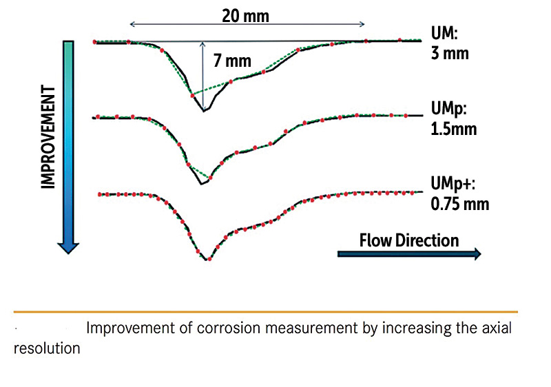
The result of these developments is an increase of a factor of two in the number of ultrasonic sensors from the old UM standard to the UMp standard. Compared to the former UM tools (0.31 inch [8 mm] circumferential resolution, 0.12 inch [3 mm] axial resolution), the current tool generation with 0.16 inch (4 mm) circumferential resolution and up to 0.75 mm axial resolution generates eight times more inspection data (UMp+ version).
High-resolution tools can detect and size tiny corrosion spots (pinholes with dimension <0.39 inch [<10 mm]), seen even in welds. The comparison of the ultrasonic image with a picture of the cut-out defect exhibits a good alignment.
Such small pinhole defects are usually not detected with legacy, standard resolution tools. Using the higher resolution tools, however, such defects are found quite frequently in many pipelines. This special type of metal loss is mainly related to the welding of the girth welds. Many of those have been confirmed by several verification campaigns in different countries exhibiting defect depths up to 80% wt.
The issue of resolution cannot be discussed without taking into account the relationship between axial resolution and the maximum inspection speed that is acceptable to ensure a specified axial resolution.

Ultrasonic Modeling
Ultrasonic modeling is being used more and more as a powerful tool for supporting and optimizing inspection solutions. Commercial products and proprietary developments are available using a variety of physical approaches. The most accurate tools from a physical point of view are based on finite element (FE) or finite difference (FD) methods.
Using the latest computer technology, even 3-D modeling can be performed in acceptable time frames (minutes to hours depending on the testing scenario). Other tools using approximations such as ray tracing allow even faster calculations. However, the intrinsic limitations of these methods need to be kept in mind.
NDT Global has developed its own modeling software based on the FD approach. The software allows for the precise modeling of many testing situations. In particular, the testing parameters (geometry, defect type, defect size, ultrasonic sensor characteristics, medium, etc.) can be easily modified to enable parameter studies in a much faster way compared to experimental studies.
For special situations, it is recommended to verify the modeling results by selected experiments. However, the appropriate usage of ultrasonic modeling can reduce costs and time. In the foreseeable future, its application will become more and more a convenient part of the development process for ultrasonic inspection solutions.
Trends
The progress of ILI will continue in the future, though the performance capabilities of the latest ILI tools have already reached a high level compared to the first-generation tools. There are several improvements that are already apparent today. Some of these were driven by developments resulting from other applications that needed additional development steps to be implemented into an ILI tool; others were driven by new challenges from the pipeline side where, for example, more difficult environmental conditions exist.
Some of the trends are briefly touched upon in the following sections.
Combined Solutions
Based on the continuous miniaturization of electronic components as well as the progress in the development of sensors used in ILI tools, a combination of several independent inspection technologies in a single tool will be one of the next targets. NDT Global used a combined metal loss and crack detection tool for the first time in 2007.
Such combination tools may also be equipped with additional inspection modules providing, for example, geometry inspection and inertial navigation systems (INS) all in one inspection.
Combined inspections offer several benefits for the pipeline operator:
■ The mob/demob and cleaning activity is required only once.
■ The different data sets are perfectly aligned. This is very helpful for data analysis (feature discrimination, evaluation of combined defects).
■ Applying two independent inspection technologies for the same feature type improves the probability of detection (POD) as well as the sizing accuracy.
Challenging Applications
Some of the most challenging applications of ILI are related to the inspection of offshore pipelines. These challenges can be categorized according to:
■ Environment: High pressure, high temperature
■ Materials: Clad pipe, lined pipe, austenitic alloys, thick wall
■ Type of line: Flow lines, injection lines, production lines, risers, dual-diameter lines
■ Medium: Crude oil, condensate, seawater
The challenges become even more demanding when the oil and gas production will proceed from deep sea into the area of ultradeep sea (depths > approx. 6,562 feet [2,000 meters]). NDT Global is prepared for these challenges having developed a variety of tools for the inspection of deep-sea pipelines. These tools are frequently applied for metal loss and crack inspection on a routine basis in offshore production fields worldwide.
Summary
The main task of inline inspection is the early detection of potentially hazardous pipeline anomalies (e.g., metal loss) as well as their precise sizing, thus providing reliable input data for integrity assessment. For the inspection of liquid pipelines, ultrasonic tools offer specific advantages with regard to resolution as well as measurement accuracy. Since the early 1980s, these tools have been considerably improved by taking advantage of the progress in electronics, data processing technology and data storage capabilities made available from other application areas.
For example, the current achieved measuring resolution allows for the reliable detection of tiny pinholes at higher inspection speeds than available in the past. Apart from progress regarding the inspection tools, ultrasonic modeling is becoming more and more important as a supporting tool for a better understanding of ultrasonic signal behavior as well as for optimizing inspection solutions.
Authors: Herbert Willems is principal ILI technology consultant; Thomas Meinzer is global manager of Data Analysis UM; Gerhard Kopp is a researcher for Software Development NDT Global, Stutensee, Germany.

Comments