
June 2019, Vol. 246, No. 6
Features
Measuring Crack Defects with Sub-Millimeter Accuracy
Ultrasonic crack technology, using piezoelectric transducers, is a proven and widely used solution for crack and crack-like defect detection in liquids pipelines. Over the past 20 years, only minor developments and improvements in this area were offered to pipeline operators.
The most significant enhancement was a move from bucket sizing to absolute depth sizing. After two decades of incremental improvements, technology-related limitations still prevent accurate sizing of defects.
Recent technical developments have successfully overcome several of these limitations. Higher-resolution tools, specialized sensors and measurement configurations address major flaw-measurement challenges: depth-sizing accuracies, extended maximum crack depth sizing beyond the formerly known maximum crack depth of typically 4 mm (0.16 inch), through wall defects, and measurement capabilities less susceptible to skew and tilt.
NDT Global’s Evo Eclipse technology is a combination of high-resolution crack robots (UCx) and new analysis methodologies. Together, these technologies enable new inline inspection robots with a circumferential resolution of 5 mm (0.2 inch).
High-resolution robots offer increased crack depth-sizing accuracy and repeatability. More importantly, they are an enabler for enhanced-sizing methodology, allowing new ways to analyze data, which successfully overcomes existing depth-sizing limitations.
Evo Eclipse sizing technology results in accurate depth values for many flaws, typically below 0.8 mm (31 mil) tolerance. A combination of different datasets, characteristics, and sizing methodologies allows highly accurate inspection, with greatly reduced tolerances. Sub-millimeter accuracy for the entire range of flaws, including hook cracks, is now possible.
Ultrasonic crack technology, using piezoelectric transducers, is a widely used solution for crack and crack-like defect detection in liquids pipelines. Over the past 20 years, only minor developments and improvements in this area were offered to pipeline operators. The most significant enhancement was a move from bucket sizing to absolute depth sizing. After two decades of incremental improvements, technology-related limitations still prevent accurate sizing of defects.
Recent technical developments at NDT Global have successfully overcome several of these limitations. Higher-resolution tools, specialized sensors and measurement configurations address major flaw-measurement challenges: depth-sizing accuracies, extended maximum crack depth sizing beyond the formerly known maximum crack depth of typically 4 mm (0.16 inch), through wall defects, and measurement capabilities less susceptible to skew and tilt.
The technology is a combination of high-resolution crack robots (UCx) and new analysis methodologies. Together, these technologies enable new inline inspection robots with a circumferential resolution of 5 mm (0.2 inch).
High-resolution robots offer increased crack depth-sizing accuracy and repeatability. More importantly, they are an enabler for enhanced-sizing methodology, allowing new ways to analyze data, which successfully overcomes existing depth-sizing limitations.
The sizing technology results in accurate depth values for many flaws, typically below 0.8 mm (31 mil) tolerance. A combination of different datasets, characteristics, and sizing methodologies allows highly accurate inspection, with greatly reduced tolerances. Sub-millimeter accuracy for the entire range of flaws, including hook cracks, is now possible
Ultrasonic crack technology, using piezoelectric transducers, is a proven and widely used solution for crack and crack-like defect detection in liquids pipelines.
Over the past 20 years, only minor developments and improvements in this area were offered to pipeline operators. The most significant enhancement was a move from bucket sizing to absolute depth sizing. After two decades of incremental improvements, technology-related limitations still prevent accurate sizing of defects.
Recent technical developments at NDT Global have successfully overcome several of these limitations. Higher-resolution tools, specialized sensors and measurement configurations address major flaw-measurement challenges: depth-sizing accuracies, extended maximum crack depth sizing beyond the formerly known maximum crack depth of typically 4 mm (0.16 inch), through wall defects, and measurement capabilities less susceptible to skew and tilt.
NDT Global’s Evo Eclipse technology is a combination of high-resolution crack robots (UCx) and new analysis methodologies. Together, these technologies enable new inline inspection robots with a circumferential resolution of 5.0 mm (0.2 in).
High-resolution robots offer increased crack depth-sizing accuracy and repeatability. More importantly, they are an enabler for enhanced-sizing methodology, allowing new ways to analyze data, which successfully overcomes existing depth-sizing limitations.
Evo Eclipse sizing technology results in accurate depth values for many flaws, typically below 0.8 mm (31 mil) tolerance. A combination of different datasets, characteristics, and sizing methodologies allows highly accurate inspection, with greatly reduced tolerances. Sub-millimeter accuracy for the entire range of flaws, including hook cracks, is now possible.
Conventional Pulse
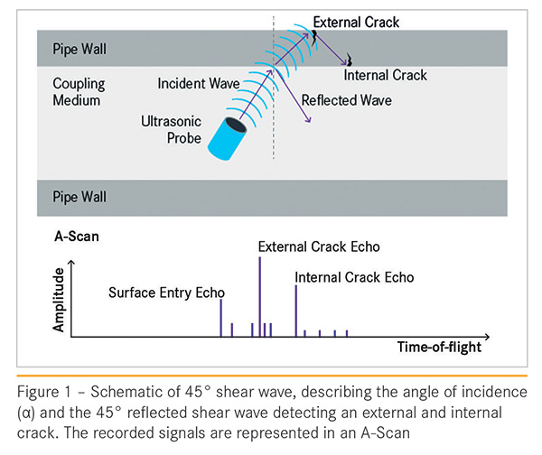
Widely used for crack detection and sizing, 45° pulse echo (PE) shear wave technology is based on an ultrasound sender/receiver configuration in which the sender and receiver comprise a single element. An ultrasonic pulse is transmitted from the sensor in a liquid coupling medium (e.g., oil, water, diesel). The signal travels through the medium and continues the sound path in the pipe wall. The system is mechanically setup to generate a 45° angle of sound path in the specimen.
Deviations from the optimum 45° angle affect the amplitude of the recorded signal and, as a result, the depth-sizing accuracy of flaws. The emitted signal could be reflected by an external or internal flaw. The reflected signal’s time of flight (TOF) or travel distance provides information about the location of the flaw: early signals represent external defects; late signals represent internal defects.
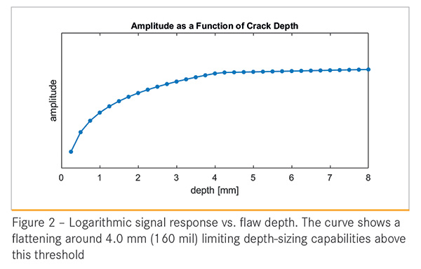
The recorded amplitude of this corner echo (CE) contains information about the depth or severity of a defect. Figure 1 depicts the described setup. Figure 2 depicts a typical sizing model for pulse echo technology. The chart clearly illustrates a flattening effect of the recorded signal from a depth of approximately 4.0 mm (160 mil) onward. This effect limits the conventional pulse echo technology in depth sizing above 4.0 mm (160 mil). (Figure 1) (Figure 2)
High-Resolution
The path leading to Evo Eclipse technology began in 2016, with the development of high-resolution crack robots (UCx) and new analysis methodologies. Together, these technologies enabled robots with a circumferential resolution of 5 mm (0.2 in). Circumferential resolution on its own is a significant enhancement to any crack inspection.
By at least doubling the number of sensors emitting and receiving signals, several aspects are enhanced (Table 1).
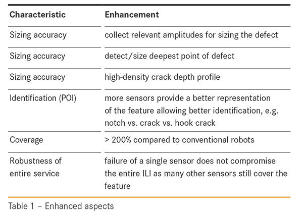
Significant improvements in four areas helped to drive the technical evolution leading to the development and successful commercialization of Evo Eclipse technology: Greater sensor density (with more channels); greater onboard processing power; greater onboard data storage capacity; and improvements in analysis methodologies, partly as the result of the availability of more and better data produced by the high-resolution robots.
High-resolution robots already offer a certain increase in crack depth-sizing accuracy and repeatability. More importantly, they act as an enabler for Enhanced Sizing methodology, and they allow for a new way to analyze data and overcome the existing limitations in depth sizing.
Tilted Cracks
Although the industry has seen dramatic improvements in ILI technology and capability since first introduced, it has lacked the ability to accurately measure tilted cracks, e.g., hook cracks or cracks following the bevel of a DSAW. In general, detecting these types of cracks with current technology is possible, but accurately sizing them is not.
Within the last year, NDT Global has overcome these remaining challenges in liquid crack detection technologies.
To address tilted and hooked cracks, a modified sensor arrangement was introduced to the fleet of robots. Instead of arranging clockwise and counter-clockwise sensors independently from each other, the new arrangement always combines a clockwise and a counter-clockwise sensor as a pair. This allows recording a third type of signal, in addition to the conventional pulse echo and enhanced sizing information.
Figure 3 depicts the general sensor arrangement. The left-hand plot shows the situation for a pipe without any flaw. The emitted signal from the TX sensor is traveling in the liquid and pipe wall, reflected at the outer wall and recorded by the RX sensor. When no obstacle, e.g. a crack, blocks or partly blocks the signal path, the maximum reflected amplitude is recorded.
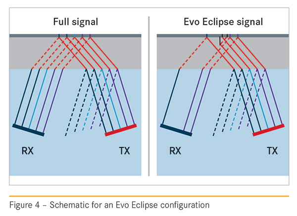
A crack, e.g. at the external pipe wall, causes a portion of the signal to be blocked or shaded, and the recorded amplitude is reduced. The technology is invariant to tilt angles. Even branched cracks are accurately sized, because they also shade the signal and block the sound path.
During development of Evo Eclipse technology, systematic simulations were performed to investigate sensitivity, amplitude behavior, and depth-sizing capabilities of this arrangement for different crack types and morphologies. Four categories were defined with different crack morphologies (Table 2).
The abscissa shows different crack types with an increasing tilt angle in each group. On the ordinate, the absolute depth-sizing error is plotted. Oversizing is reflected by positive values, under sizing by negative values. Pulse echo results are represented by squares. Circles indicate the result of the sizing methodology. For each color/category, the design crack depth values from left to right are increasing. The number next to the symbol indicates design depth.
As expected, the error in crack depth for conventional pulse echo technology is low for notches < 4 mm (160 mil) and Type A cracks with radial main component and a small hook only. As soon as the main component is not oriented in radial direction or combined with a longer second crack component, the sizing capabilities are significantly reduced. Typically, this leads to an under sizing of flaws.
In comparison, Evo Eclipse sizing results in accurate depth values for many flaws, typically below 0.8 mm (31 mil) tolerance. A few outliers show oversizing of depth. The selected geometries of those features represent Category C cracks. For all these features, the axial component is significant compared to the radial.
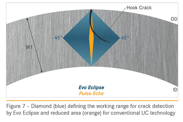
Some of these defects are closer to a lamination than a conventional crack. These findings led to the definition of a diamond or rhomb. Cracks, whose tips are within the indicated rhomb area – starting at the OD or ID intersection with the diamond – can be detected and accurately sized (Figure 4).
Conclusion
A combination of different datasets, characteristics, and sizing methodologies allow a highly accurate inspection service, with greatly reduced tolerances. Sub-millimeter accuracy for the entire range of flaws, including hook cracks, is now possible.
Pipeline operators can now get a far more accurate understanding of their pipeline condition, without assuming the costs and risks of hydrostatic test inspection. P&GJ
Authors: Thomas Hennig is technology advisor for NDT Global in Dublin, Ireland; Rogello Jesus Guajardo is global manager, Data Analysis UC, and Michael Haas is physicist at NDT Global in Stutensee, Germany


Comments