
February 2019, Vol. 246, No. 2
Features
Combined Flaws Represent Key Danger to Pipelines
P&GJ Staff Report

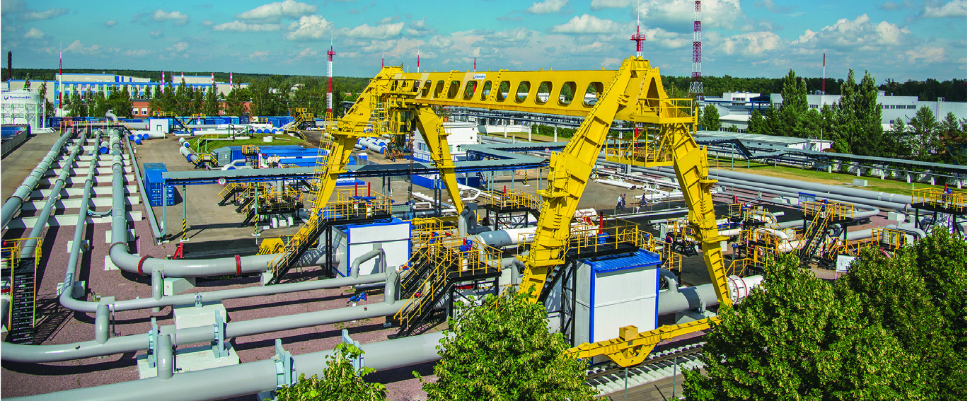
Sergey Zubin, chief engineer of Transneft Diascan, discusses the importance of detecting “combined flaws,” or those that occur in close proximity on the pipeline, with Pipeline & Gas Journal.
His company provides research and development services, as well transporting crude oil and oil products.
P&GJ: What are combined flaws?
Zubin: Combined flaws are combinations of separate discrepancies that do not meet the standard requirements of the wall, geometric shapes of the pipe and welded seams on a limited part of the pipeline. According to the regulatory documentation of PJSC Transneft, combined defects are two or more closely spaced flaws of various types.
For combined defects the minimum distance from the edge of one flaw to the edge of the other is less than or equal to four thicknesses of a defect-free pipe wall in the area adjacent to the defect. While the distance between the flaws is regulated, the types of defects can be different. These include any possible combinations of pipe shape defects, pipe wall defects and weld defects. For example, such combinations as dent-gouge, dent-crack, dent-corrosion, dent with weld seam defect, lamination with corrosion, etc.
P&GJ: Why are combined defects dangerous?
Zubin: During operation, the pipe is exposed to aggressive effects of oil and gas products, pressure and temperature changes, soil, groundwater and surface water. These factors inevitably result in corrosion, as well as the geometry defects and cracks. Another significant problem is the pressure taken by the pipe wall, which can also lead to its gradual deformation.
If the defect is combined, additional pressure concentrators arise. The risk of pipeline deformation in the area of this flaw type increases many times. This represents the key danger of the combined flaws.
Often one flaw grows into another one. For example, a crack progresses from the initial gouge into a dent. Specialists distinguish flaws combinations that can be less or more dangerous. The most dangerous combinations are dent-crack and dent-gouge.
Generally, cracks result from the gouge that was initially in the dent. When operating the pipeline, the internal cyclic pressure in the pipe tends to straighten the dent. At the same time significant tensile pressure arises at the root of the gouge. It provokes a crack in the hard metal with reduced ductility.
P&GJ: Why are standard one-section tools not as effective in identifying combined defects?
Zubin: Single-section or discrete tools, per se, are quite effective in detecting flaws. Each discrete tool is developed to identify a certain type of flaw. For example, ultrasonic inspection tools detect corrosion, lamination, gouges, and misalignment of edges in welds.
Magnetic flaw detectors with longitudinal magnetization are aimed at detecting pitting corrosion, scratch marks, crack-like defects in girth welds and pipe body. Corresponding tools with transverse magnetization are used to identify longitudinally oriented defects, including longitudinal welds.
To detect all possible types of defects specialists used to run several types of inspection tools sequentially. However, this approach has several significant drawbacks. The fact is that during sequential runs, the conditions in the pipeline such as pressure, speed and temperature change. Therefore, the accuracy of this method is not high enough. Additional measures must be undertaken to prepare the pipeline for the run of the inspection tool.
P&GJ: What is the working principle of the combined inspection tools? What are their advantages compared to one-section models?
Zubin: Combined flaw detectors are inspection tools combining several different sections that identify a certain range of flaws simultaneously. As I have already said, when sequentially running discrete tools and reconciling the data, it is necessary to take into account different inspection conditions.
There is no need for that if combined inspection tools are used: just one run provides more reliable information due to avoiding temporary lag between successive runs of inspection tools based on different operating principles. The data obtained from each section corresponds to the same operation parameters. During the run the pressure, speed and the temperature in the pipeline are identical.
The data from sensors of the combined tool’s sections is georeferenced as one defect is simultaneously detected by two or more non-destructive control methods. Due to this approach, reliability of the flaw detection and accuracy of flaws parameters are much higher compared to the data received from the discrete tools.
The accuracy of the data obtained is important for further strength calculations, assessment of flaws’ danger, suitability of the pipeline and its lifetime. Thus, we can say that combined flaw detectors are the most effective group of inspection tools ever.
P&GJ: What types of combined inspection tools exist? What tasks does each of them solve?
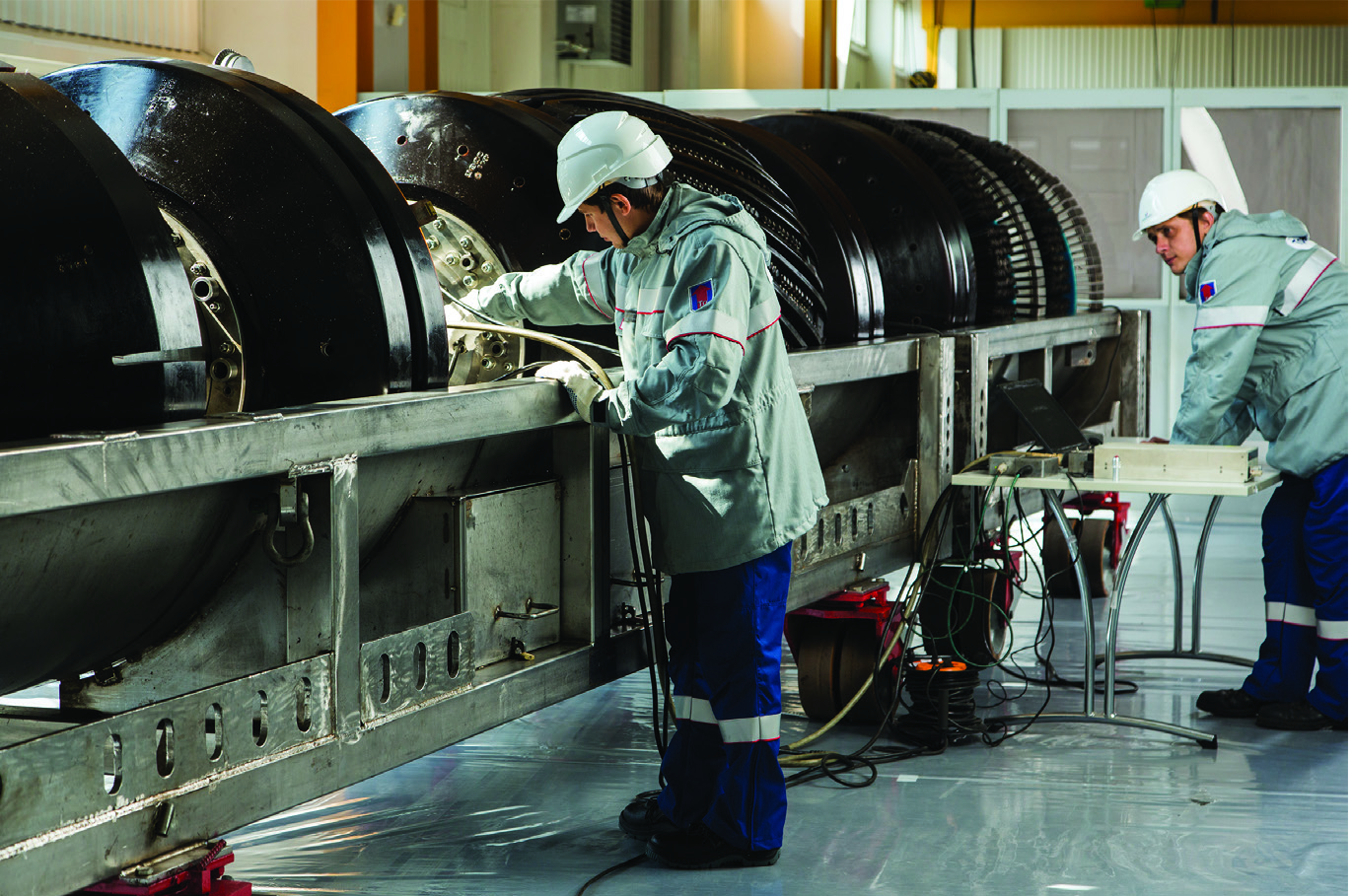
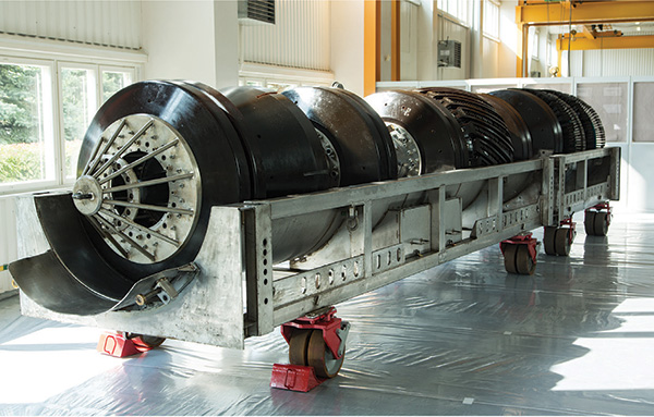
Zubin: Transneft Diascan’s fleet of combined inline inspection tools includes models of various diameters from 6 inches to 48 inches. The design department of the company, which turned 17 this year, has created around 90 operating tools, including combined magnetic and combined magnetic-ultrasonic flaw detectors.
The first type, the combined magnetic flaw inspection tool, allows the accurate detection of various types of flaws, including illegal tapping and welded seam flaws due to both longitudinal and transverse magnetization. The second type, the combined magnetic-ultrasonic flaw detector, allows carrying out both magnetic (MFL) and ultrasonic (WM and CD) inspection in just one run, detecting metal losses as well as longitudinally and transversely oriented cracks.
P&GJ: How can an operator choose the right type of the inspection tool?
Zubin: Usually the operator of the pipeline expects to identify certain types of pipe defects typical for particular operational conditions. Terrain, soil, chemical composition of the pumped product are significant factors triggering typical flaws. The dynamics of the flaw growth, monitored by pipeline integrity management programs, indicates the need for one or more types of inline inspection.
Thus, when choosing an inspection tool, the operator should first and foremost take into account the types of expected pipeline flaws, the required volumes and rates of pumping and the corresponding parameters of the allowable pressure. Since each type of flaw has a certain method of technical identification, the type of inspection tool is also determined depending on the tasks of the operator. The tasks can be completely different: from pipeline commissioning and regular inspection to maintain its operation to re-inspection of previously identified flaws or creation of a pipeline integrity management system.
Another combined tool is a magnetic-ultrasonic flaw detector. Carrying out both MFL and ultrasonic inspection in just one run, the tool effectively combines the advantages of both methods. It detects longitudinal cracks, longitudinal and transverse welds flaws, pitting corrosion, lamination, metal losses and gouges.
P&GJ: How do the costs of the combined tools operation differ from the costs of one-section tools inspection?
Zubin: The cost of running one combined flaw detector is higher than using a single principle tool. However, the costs of running, processing and analyzing the data of a combined pipeline inspection are lower than the sequential running of two or more discrete tools. Thus, the combined inspection tool is the most cost-effective solution when it comes to detecting flaws of several types.
P&GJ: What smart technologies are used to analyze the data obtained during inline inspection?
Zubin: All data is processed in a specialized analytical center. Based on this information, our specialists create technical reports and give recommendations for further operation of the pipeline.
The company’s technological solutions include digital information and an analytical system called “Defect.” The system stores all the information from Transneft Diascan inline inspection practice since 1997. The data includes parameters of the detected flaws, strength and durability calculations, information on flaw repair works and other data.
All analytical reports of the company comply with the international standards and recommendations of the Pipeline Operators Forum (POF). Optimization of the inline inspection capabilities by introducing the latest technological solutions is one of the company’s priorities.
P&GJ: What is the future of the inspection equipment development in your opinion?
Zubin: At the moment we can highlight two trends in the development of inspection equipment. The first one is an increase in the capabilities of the hardware component of inline inspection tools.
While improving the flaw detectors, the parameters for detecting minimal flaws are reduced, which allows dynamic tracking of the defect until it reaches a critical level. If earlier tools collected only the data on the state of the pipe wall and welded seams, the newest models allow identifying coordinates of the flaws and other pipeline features: absolute distance, distance from the girth weld, orientation, and others.
Another trend is directly related to the combined inspection tools. The number of measuring channels has been increasing, and the scanning step has been reducing. Thus, the data is collected more often during the movement of the tool through the pipe. Today, leading market players provide a 1.5 mm scanning step, which is more than two times lower than the standard indicators of 3.3 mm.
As for the possible replacement of discrete tools with the combined ones, this has already happened in terms of regular pipeline inspections. However, when solving complex problems where all-purpose equipment cannot be sufficiently effective, special discrete inspection complexes will still be applied and developed. In addition, pipeline operators often decide on the type of required inspection. For example, they choose only MFL. In this case, running combined flaw detectors is unreasonable. P&GJ

Comments