
February 2016, Vol. 243, No. 2
Features
Ultrasonic Metering, Creative Insulation Engineering, Aid LNG Plant
A major East Coast storage facility for liquefied natural gas (LNG) had a flow metering challenge on one line. The problem was directly related to the temperature of the product. LNG is liquefied to concentrate its volume for shipping and, as a result, the temperature of the liquid drops to a cryogenic minus 265 degrees Fahrenheit, which must be maintained throughout the storage facility and delivery system.
Challenges of LNG Storage
With the introduction of fracking for natural gas in the U.S. and the subsequent drop in prices, LNG storage facilities which import gas have fallen on hard times. Fortunately, this plant has found some solutions. The latest has been obtaining permission from the federal government to export the gas it buys from foreign suppliers. Since U.S. laws prohibit exports of oil or natural gas that has been produced domestically, this offers the storage facility a large potential foreign market. Their mainstay for profitability in recent years, however, has been to supply power plants during demand peaks. The facility has access to an impressive array of delivery piping to provide gas quickly to power plants and profit from the increased prices created by peak demand.
The Metering Problem
But, as mentioned earlier, flow metering hampered its efficiency. As management consultant Peter Drucker famously said, “If you can’t measure it, you can’t manage it.”
The measurement culprit in this case was a vortex meter that simply was not designed for this harsh environment. The extreme cold caused the intrusive meter to fail often. Shutdowns were extremely expensive because the LNG had to be maintained at minus 265 degrees Fahrenheit to keep it from transforming back to a gas, expanding, and causing catastrophic damage to the piping. After several of these maintenance shutdowns, management sought another measurement technology.
An Ultrasonic Possibility
The engineering team turned to Flow Tech, a distributor they had worked with for years. They act as a manufacturer’s representative and stocking distributor of process instrumentation and calibration equipment providing technical sales, systems, and service. They specialize in the test/measurement fields.
“At this time, one of our suppliers, FLEXIM Americas, had developed a device that enabled them to accurately measure both very low and very high temperature environments,” said Travis Teeter, industrial sales engineer at Flow Tech.
How Ultrasonic Flow Meters Work
“Ultrasonic flow meters, unlike traditional meters, contain no moving parts and don’t need frequent calibration and maintenance,” explained Izzy Rivera, FLEXIM Americas’ sales engineer and technical specialist. “Measurements are made using the transit-time difference method. It exploits the fact that the transmission speed of an ultrasonic signal depends on the flow velocity of the carrier medium. An ultrasonic signal moves slower traveling against the flow direction of the medium and faster when it is traveling in the flow direction,” he said.
For the measurement, two ultrasonic pulses are sent through transducers clamped to the pipe and into the medium, one in the flow direction and the second against it. The meter’s transducers work alternately as transmitter and receiver. The transit time of the signal sent in the flow direction is shorter than that of the signal sent against the flow. The meter measures the transit time difference and calculates the average flow velocity. Because the ultrasound signals propagate in solids, the meter can be mounted directly onto the exterior of the pipe non-invasively, Rivera said.
“These ultrasonic flow meters are not affected by density, which make them ideal for multiple applications from slurries to gas measurements,” Rivera said. “They can automatically compensate for variations in viscosity. Using sound speed for information, they can also detect liquid type and density in an application where multiple products flow in the same pipe.
“We had recently patented a device that holds our flow meter’s transducers about four inches from the LNG pipe we want to measure. Our meter and transducers could only measure accurately down to about minus 40 degrees Fahrenheit. By placing the transducers away from the pipe, we could still send an ultrasound signal into the flow and keep the temperature of the transducers well above minus 40 degrees. We thought we had opened a market – LNG flow measurement – that had been closed to us by temperature constraints. We had already opened high-temperature applications with the same device. But it was different with LNG,” Rivera said.
The problem was that LNG had to be kept at minus 265 degrees Fahrenheit or it would expand and increase the vapor pressure of the stored liquid. So, the pipes are well-insulated to reduce heat infiltration and sealed to prevent moisture from entering the insulation. If moisture comes in contact with the pipe, it quickly forms an ice ball that grows in size as more moisture is present, he said.
“We did what we thought was a thorough job of insulation, but we didn’t allow adequately for moisture. Ice kept forming on the transducers causing failures. We had tried a variety of tapes and plastics, but the moisture kept finding a way in,” Rivera recalled.
An Engineering Solution
Enter Alan Hatfield, vice president of LNG Technical Services at Braemar Engineering in Houston who met Rivera at a trade show and inquired about the meter’s performance in very cold environments.
 “It turned out they were working on an installation at a big LNG storage facility and were having some troubles with the installation because moisture was getting into the insulation and forming ice on the surface of the meter‘s transducers,” Hatfield recalled.
Rivera learned from Hatfield about Braemar’s work with LNG applications, ranging from new plant construction to all types of maintenance challenges, and was advised that he needed more information, including the dimensions of the metering equipment, compositions of the pipe and transducers. Shortly afterwards, Rivera and his team hired Braemar Engineering to come up with an insulation and vapor- protection solution.
“The key was that they didn’t have the proper vapor-barrier configuration that prevents convection and completely seals out moisture. Quite simply, they needed a barrier that seals out all airflow within the insulation. They were preventing conduction but not convection,” said Hatfield.
The Braemar team recommended polyisocyanurate (PIR) pipe insulation, a polyurethane-modified polyisocyanurate cellular plastic supplied as a bunstock foam. PIR was chosen because it provides dimensional stability over a wider range of temperatures than standard polyurethane insulation, plus it does not provide nutrients for mold and mildew, Hatfield explained.
The rigid foam can be fabricated into sheets and other shapes for a variety of thermal insulation and specialty applications with higher strength requirements. Shaped as pipe insulation, PIR has been used extensively in extreme environments and has proved an excellent performer in cryogenic applications, including LNG, he said.
Environmentally, it is manufactured without chlorofluorocarbon or hydro-chlorofluorocarbon blowing agents. In accordance with the Clean Air Act and the Montreal Protocol, PIR foam insulation is manufactured with hydrocarbon blowing agents, which has no ozone depletion potential, Hatfield said.
Though the performance and safety of the PIR was extremely important to the project, it was the lack of a vapor barrier that caused problems with the original installation, he said. The purpose of the vapor barrier was two-fold. First, it had to protect the outer layer of the PIR installation from ultraviolet light from the sun and seal it from any moisture penetration. They specified stainless steel metal weather jacketing applied with a minimum of two coats of a mastic material.
Second, they recommended a secondary vapor barrier between the outer PIR layer and the inner. This extra layer would ensure that absolutely zero moisture could reach the flow meter’s transducers. It consisted of a three-layer multiplex with a layer of aluminum foil sandwiched between two layers of polyester film.
Rivera said they contacted the insulation contractor recommended by the LNG storage facilities engineers, and they followed the insulation specifications created by the Braemar engineering team.
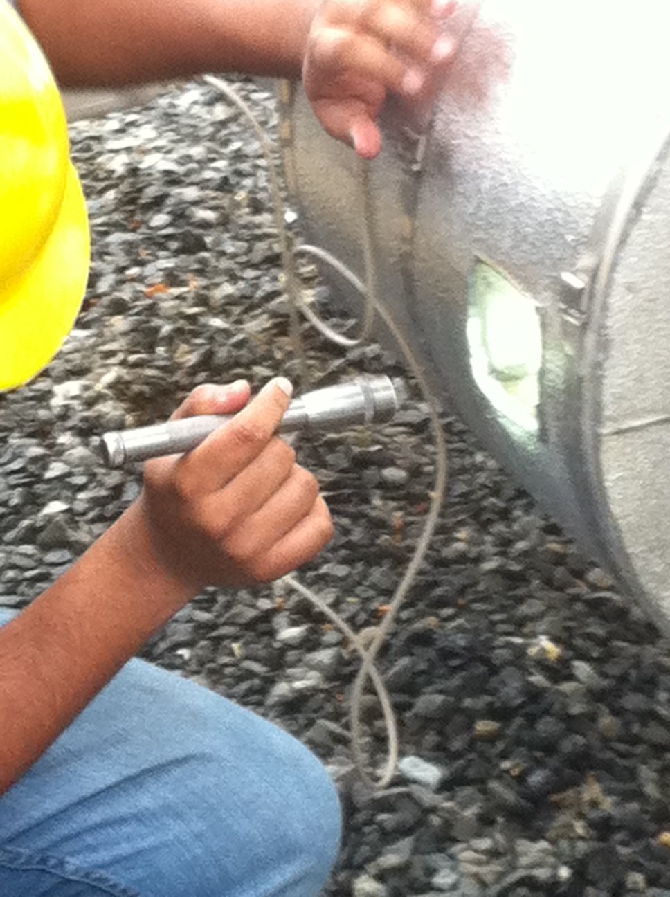
“They even included an insulated window so we could visually monitor the transducers,” Rivera recalled.
“As a result of the insulation solution provided by Braemar, the original meter has been working accurately ever since we completed the new insulation installation with no need for service and engineers at the LNG storage facility have ordered two more ultrasonic flow meters to monitor their main line 32-inch pipe used for offloading LNG from the ships.
“It wasn’t easy,” Rivera said, “but, with the help of insulation engineering, we have finally found an ultrasonic solution for extra low temperature flow applications.”

Comments