
July 2015, Vol. 242, No. 7
Features
Best Practices for Mitigating Flow Measurement Errors Associated with Hydrate Formation
Operating pipelines at high pressure and low temperature can lead to natural gas hydrate formation, even with modest water content. Hydrate formation is also a growing concern as flow measurement equipment and operators become more accustomed to handling wet gas flow.
Hydrate particles can attach to pipe walls, instruments, and other structures within the pipeline, which can then lead to gas measurement errors or instrument failure due to solid particle attachment or high-velocity impacts.
Hydrates can also agglomerate and form plugs that can lead to a total flow blockage, which can be a serious safety and operational concern for pipeline operators. This article will discuss the operating conditions that allow hydrates to form, how they can affect flow measurement, methods for reducing formation processes, and their impact to overall process safety.
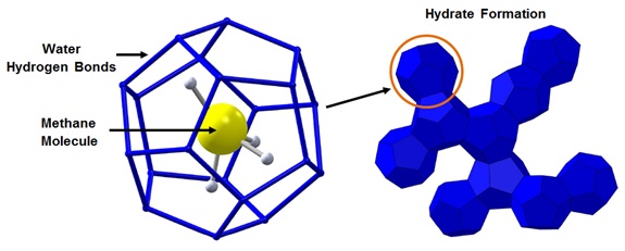
Natural gas hydrates are “ice-like” solid crystalline structures composed of water and natural gas. The gas molecules (guests) become trapped in water cages (hosts), also known as clathrates, at high pressures and low temperatures. Hydrates have similar mechanical properties to ice but can form at temperatures well above the freezing temperature of water. In natural gas flows, the typical guest molecules are methane, ethane, propane, and carbon dioxide.
Natural gas hydrates typically form two crystalline structures: Structure I and Structure II (also known as Type I and Type II). The type of structure formed is dependent on the guest molecule size. Structure I hydrates are more prevalent in natural gas flows because they form with methane, ethane and carbon dioxide molecules.
Figure 1 shows the molecular structure of a Structure I methane hydrate. Both Structure I and Structure II cages are about 85 mole percent water. The nominal composition of methane hydrates is 5.75 moles of water per one mole of methane: (CH4)4(H2O)23. Methane hydrate density is about 56.2 lb./ft3 and one cubic foot of methane hydrate solid would contain 188 standard cubic feet of methane.
Hydrates were first discovered in a laboratory setting in the early 1800s but did not impact the energy industry largely until the 1920s when natural gas was first transported over long distances in pipelines. During production in cold weather, the pipelines would become blocked with what appeared to be ice, but the temperatures were above typical freezing conditions for water.
In the 1930s, Hammerschmidt first recognized that the blockages were hydrate plugs forming in the line at temperatures above the ice point.
This discovery led to the regulation of water content in the pipelines and the use of thermodynamic hydrate inhibitors to suppress the formation of hydrates. Even with inhibitor use, hydrate blockages continue to be a top flow assurance problem in oil and gas operations. Figure 2 provides a photograph of a hydrate plug that was removed from a pipeline.
Hydrate Formation Conditions
Hydrates form under (relatively) low temperature, high pressures and when water is present in the system. A hydrate formation curve can be utilized to determine if the process conditions can support hydrate formation. A hydrate formation curve is unique to the gas composition in the pipeline. Hydrate formation curves can be generated using industry-standard software packages such as HYSYS®, PVTsim® and Multiflash®.
Hydrate formation curves can also be estimated by using the guidelines provided in Section 20 of the Gas Processors and Suppliers Association (GPSA) Handbook. Natural gas that contains heavier molecules, such as propane and isobutane, will form hydrates at higher temperatures (Structure II crystals). Figure 3 shows the range where gas transmission lines typically operate, and it is surprising to many gas transmission operators when they learn that hydrates can form even at moderate temperatures (50°-60°F) under high pressure conditions.
Hydrates also require water to form and the gas or liquid must be at or below its water dew point or saturation condition. It is also important to note that condensed water is not required for hydrate formation and hydrates can form from water vapor.
Water in natural gas pipelines usually comes from two sources: residual hydrostatic test water and produced water from the reservoir. “Sweetened” natural gas may also contain significant amounts of water due to the use of aqueous solutions to process acidic gas. Separation of the water and dehydration of the gas normally occurs downstream of the wellhead, but significant water content can still be present in the system if the separation systems fail.
Section 20 of the GPSA handbook also discusses inhibitor best practices for reducing or suppressing hydrate formation for cases when water separation is not practical or economical. Glycols or methanol can be injected into the process stream and must come in contact with the condensed water prior to achieving hydrate formation pressure and temperature.
Figure 4 shows the hydrate suppression effect that a methanol injection has on a high-pressure pipeline from wellhead to its distribution manifold, with a 5°F temperature depression margin.
Once hydrates form, they have a tendency to “stick” or agglomerate into larger particles through capillary forces. Agglomeration is also enhanced in turbulent flows, mixing, and agitation of the gas and liquid. Hydrates usually attach to pipe walls first and then build thickness when hydrate formation conditions persist.
Process Effects with Formation
Hydrate formation can have several different effects on natural gas transmission processes. Operators should understand their “normal” operating conditions (e.g., pressures, temperatures, flow rates, etc.) to better identify when hydrates may form in their process lines. There are several process changes which can occur from hydrate formation. Detecting these changes is a function of the rate at which hydrates are forming in the process, the instrumentation employed in the process, and the data logging frequency.
As hydrates form, gas molecules become “trapped” in the crystalline cages and, therefore, consumed in the process. During consumption, the static pressure is reduced in the system and will lead to a mass imbalance between metering stations if enough hydrates form.
Reviewing flow meter and pressure logs for a reduction in flow or operating pressure can help operators identify locations where hydrates are forming. Water is also consumed during hydrate formation. Hence, operators can review the water content in dehydration facilities or water traps to determine if the amount of water expected in these facilities is less than normal.
Hydrate buildup on pipe walls reduces the effective area of gas flow, thus increasing the pressure drop of the system.
Detecting an increase in pressure drop is likely the most effective method for determining hydrate buildup in the system because compressor power consumption or rotational speed is usually a readily available parameter. Detecting a reduction in flow rate at constant compressor speed is also another method for determining hydrate plugging in the system.
Care is required to ensure that pigs are not stuck in the lines due to increased friction from excessive hydrate buildup. Hydrate deposits vary in rheological properties, but resistance to deformation is dependent on the fluids in the process. Typically, gas-dominated flows with water-saturated gas result in much harder deposits than flows where liquid content (especially liquid hydrocarbons) is present.
Hydrate formation is also an exothermic process. If continuous buildup on pipe walls is occurring or hydrates are forming at a high enough rate, detecting a local temperature change could assist the operator in locating the source of a buildup. This detection method is likely the most challenging due to the ambient heat loads and internal forced-convection heat transfer, which quickly dissipates the heat of formation to the rest of the system.
Local heat sources from hydrates would likely not yield enough change in temperature for detection by point measurements of temperature, but detecting changes in temperature along the length of a pipeline could assist the operator in locating any hydrate formation and increases the probability of detection.
Recent and ongoing research at SwRI using distributed temperature sensing (DTS) with fiber-optic cables has investigated the application of detecting temperature changes from hydrate formation. Early results indicate that local temperature changes on the order of 1.8° F would likely be detected by a DTS system.
Flow Metering Effects with Hydrate Formation
Natural gas hydrates have a tendency to agglomerate and attach to surfaces inside the process pipe and that could adversely affect flow measurement and gas sampling systems. Liquid water in the pipeline can collect in front of (or behind) the orifice plate. and when the system temperature drops, hydrates will form on the gas/liquid interface.
Gas-shearing forces can cause the hydrate particles to further attach to the plate and affect the surface roughness of the plate and the bore diameter of the orifice. Reducing the bore diameter will increase the pressure drop of the orifice meter and report incorrect mass flow.
Although test data that show the magnitude of error due to hydrate buildup could not be located, previous studies have shown how the buildup of valve grease on the orifice plate, which would likely produce a similar effect to a hydrate buildup, can result in errors greater than 10%.
Hydrates can also accumulate in impulse tubing for static and differential pressure measurements that could result in blocking off a tube. Minimizing the impulse tubing length, mounting the tubing to allow for draining of liquids, and heat tracing the tubing can reduce the likelihood of this problem occurring. Regular draining of the orifice meter run can also minimize the risk of hydrate formation affecting the flow measurement.
Similar to orifice meters, Venturi and other pressure-differential type flow meters are susceptible to the same buildup of hydrates within the meter bodies and impulse tubing. Flow conditioners can also become blocked when process conditions favor the formation of hydrates, such as wet gas flow or conditions when the gas is saturated with water.
Coriolis flow meters depend on the measurement of the frequency of vibrating tubes to determine the flow rate through the meter. When solids attach to the tube walls of the flow element, this can affect the resonant frequency of the tubes, which can result in mass flow measurement errors. Advanced diagnostics within the Coriolis firmware may be able to identify this problem or the operator may be able to track off-nominal drive gain of the vibrating tubes to determine error conditions.
Ultrasonic gas flow meters use sets of ultrasonic transducers to determine the velocity of the gas along individual acoustic paths from which volumetric flow rate can be inferred. In wetted ultrasonic flow meter designs, hydrates have the potential to attach to the transducer surfaces and impede the transit time measurement. Modern ultrasonic flow meters have advanced diagnostics that can alert the meter operator when the ultrasonic signal is in an error state or if the signal-to-noise ratio is too low, resulting from solid adhesion to the transducer surface.
Shearing forces inside the process lines can also break off “chunks” of hydrate into the flow stream. High-velocity hydrate particles may stay suspended long enough to collide with measurement instruments such as thermowells or turbine flow meter blades, which can lead to damaged equipment. In extreme cases, hydrate plugs can dislodge from the pipe wall and severely damage downstream pipe elbows, intrusive instruments, and other flow measurement equipment.
Removing Hydrate Plugs Safely
Under the right conditions (i.e., source of water, high pressure, and low temperature), hydrates have the potential to build up on pipe walls over time and agglomerate into a hydrate plug in a pipeline, which is a serious safety concern. Hydrates can be dissociated by dropping the pressure in the system. It is important to avoid single-sided depressurization to prevent a hydrate plug from turning into a hydrate “bullet.”
During depressurization, it is known that hydrates dissociate at the wall first. Hydrate plugs can then dislodge, due to high differential pressure, and the resulting momentum of the moving plug can damage pipeline components and, potentially, cause human injuries or even fatalities if catastrophic damage results.
Raising the local temperature of a hydrate plug can dissociate the hydrates. However, as is shown graphically in Figure 10, this should be done with careful consideration of the fact that local heating can form high-pressure gas pockets from dissociation. The volume ratio of the hydrate solid to gas is about 200:1.
If confined, one cubic foot of dissociated hydrate can yield a local pressure of up to 37,000 psi, which can rupture the pipe wall. If one knows the exact size of the plug, it can be melted safely, but it is generally safer to use two-sided depressurization to eliminate the plug from the system.
Water Content Monitoring
Minimizing water content in natural gas flows is the most effective method for reducing hydrate growth. Several instruments are available for measuring water content in natural gas pipelines. The Bureau of Mines chilled mirror device was originally created to measure the water vapor dew point of a natural gas supply so that its water vapor content could be determined using an ASTM standard correlation. However, the time required for setup using this method makes it impractical for regular moisture measurements to avoid hydrate formation.
Several models of automated moisture analyzers are available that use a variety of technologies. These include electrolytic devices, capacitance sensors, laser-based analyzers, vibrating crystal sensors and automated chilled mirror devices. Although none of these technologies are governed by natural gas industry standards, any of them can provide online, continuous monitoring of moisture levels.
Conclusion
We have given a very brief summary of a broad subject. The interested reader is directed to the referenced documents and open literature for more detailed information. GPSA Section 20 is a great resource for predicting and controlling hydrate formation.
If hydrate formation in your process lines is not affecting your operations, then it is most cost-effective to leave the hydrates alone and they will dissociate as the process temperature of the system rises past the formation temperature.
However, hydrate buildup over time in low-temperature operations can raise the risk of forming a total blockage in the pipeline. Minimizing the water content is the key to minimizing hydrate formation effects in the system.
In the years ahead, expect the diagnostic capabilities of flow measurement equipment to improve with regard to detection of faults, such as hydrate attachment to electronic components. Hydrate inhibition mechanisms and best practices are also heavily researched topics that can provide methods for preventing or reducing hydrate formation in wet gas conditions.

Figure 2: Hydrate plug removed from a flowline. Photograph courtesy of Petrobras

Figure 3: Natural gas hydrate formation curve.

Figure 4: Example Pipeline Profile With and Without Hydrate Inhibition.

Comments