
April 2015, Vol. 242, No. 4
Features
Design, Siting Considerations for LNG Facilities
With the increase of natural gas production throughout the United States, the LNG market is growing at a rapid pace. Due to that growth, there has been a significant increase in development of small-scale, mid-scale, and large-scale LNG facilities, as well as expansion opportunities of existing facilities.
Proper design of a facility concept will start with the application of good engineering practices and relevant design standards followed by a preliminary siting and feasibility study to determine whether a particular parcel of land is appropriate for the proposed project.
While the applicable design codes for proper design are generally clear, the appropriate requirements and approved models for siting are often less clearly defined and can vary, depending on who has jurisdiction over the proposed facility.
Design Codes
During the early stages of any facility design, the developer must first determine the authority having jurisdiction and the required design codes for the facility. Currently, the applicable design code for a facility can significantly impact the siting requirements and the associated plant footprint. Depending on many variables, a small-scale, mid-scale, large-scale, bunkering or peak-shaving facility can have different design and siting code requirements and permitting paths.
The Federal Energy Regulatory Commission (FERC) is responsible for authorizing the siting and construction of onshore and near-shore LNG import or export facilities under Section 3 of the Natural Gas Act. If the facility is connected to a natural gas pipeline that is governed by 49 CFR, Part 192, that facility, regardless of size, falls under the jurisdiction of the Department of Transportation (DOT) Pipeline and Hazardous Material Safety Administration (PHMSA) 49 Code of Federal Regulations Part 193.
A caveat to the Part 193 governance is in force if a facility is the end consumer of the LNG that is brought into or produced by the facility. For example, if an import terminal was connected only to an on-site, co-generation power plant, and no natural gas was sent off-site, the facility would not fall under the jurisdiction of PHMSA because the power plant would be the end consumer of the LNG.
When a facility falls under the jurisdiction of PHMSA, the project must be built in compliance with 49 CFR, Part 193, the federal Safety Standards for LNG Facilities. 49 CFR, Part 193 incorporates by reference the National Fire Protection Association’s 59A-Standard for LNG facilities (2001 edition).
It must be noted that the current edition of NFPA 59A was published in 2013 and differs from the 2001 edition in several aspects, as it reflects the many technical improvements made in the LNG industry over the past 12 years. However, as 49 CFR, Part 193 has not been updated to incorporate more recent versions of NFPA 59A, facilities under PHMSA jurisdiction must follow 49 CFR, Part 193 and NFPA 59A (2001) as incorporated by reference.
For a facility determined to be non-jurisdictional to PHMSA, a local or state agency will typically be the authority having jurisdiction. Those local agencies may be the state public utilities commission (PUC), fire marshal or environmental department. These non-PHMSA jurisdictional facilities can be designed to NFPA 59A (2013).
PHMSA Jurisdiction
In the event that an LNG facility is determined to be under the jurisdiction of PHMSA, the siting requirements would be significantly different from those only under a state or local authority having jurisdiction. Among the most notable differences are the requirements for the determination of vapor dispersion exclusion zones.
As incorporated by reference into 49 CFR, Part 193, NFPA 59A (2001) requires the exclusion zones for flammable vapor dispersion be determined from vapor dispersion associated with LNG tank impoundments and design spills. NFPA 59A (2001) also requires the DEGADIS or FEM3A models to be used to calculate vapor dispersion distances, however formal interpretations by PHMSA have imposed additional requirements, requiring other models to calculate vapor dispersion exclusion zone distances.
Following the publication of the March 2009 report, “LNG Source Term Models for Hazard Analysis: A Review of the State-of-the-Art and an Approach to Model Assessment,” PHMSA issued a written interpretation on July 16, 2010, requiring that “in addition to analyzing the effects of vapor dispersion from LNG pool spills, the effects of ‘jetting and flashing’ releases must also be considered in calculating the vapor gas dispersion exclusion zone.”
Although the DEGADIS model can calculate vapor dispersion distances from LNG pool spills, it cannot calculate dispersion resulting from a jet release. Therefore, following petitions by the developers and a thorough review of their validation against the model evaluation protocol, in October 2011, PHMSA approved the use of two new models (PHAST v6.6 and 6.7 developed by Det Norske Veritas (DNV) of Oslo, Norway, and FLACS v9.1 developed by Gexcon AS of Bergen, Norway to calculate vapor dispersion exclusion zone distances.
The new approved models are able to model jet releases as well as liquid spills, effectively replacing DEGADIS as the modeling tool for LNG facility siting for 49 CFR, Part 193 facilities.
Due to the high momentum of the release, jetting and flashing scenarios have become the typical bounding cases for facility siting, supplanting the thermal radiation hazards associated with a tank impoundment area fire. As a result, a combination of the PHAST and FLACS software tools can be used to provide a preliminary indication of whether a piece of real estate being considered for an LNG facility covered under 49 CFR 193 will likely be sufficient to accommodate the exclusion zones.
This is a critical step for developers to perform at an early stage to ensure that a piece of real estate will be able to meet the exclusion zone requirements of 49 CFR, Part 193 before significant engineering design and capital have been invested.
As a roadmap for performing vapor dispersion during a preliminary siting analysis, the PHAST model can be used as an initial screening tool to determine the unmitigated, unobstructed dispersion distances for the various flashing and jetting scenarios. Since PHAST cannot account for the presence of obstacles or obstruction to the air/vapor flow, these results can be often considered conservative and thus present a likely upper bound to the real estate requirements for the facility.
The results of the PHAST analysis are independent of wind or release direction, and therefore the calculated dispersion distances can be easily plotted on a property survey of the facility that illustrates the general location of all major equipment, including marine facilities, LNG and refrigerant storage, regasification, liquefaction and LNG or refrigerant truck-loading.
The resulting plots will illustrate potential problem areas that may need to be mitigated using passive mitigation techniques, such as vapor fences or walls, during refined analysis, help to make changes to the preliminary layout of equipment and illustrate problem areas.
If the results of the PHAST analysis are unfavorable and additional modeling is necessary, the computational fluid dynamics (CFD) model FLACS can then be used to solve the problems identified by the PHAST modeling, which can:
• Obtain more accurate results for critical scenarios, such as scenarios that extend too far when using PHAST or could be significantly affected by equipment, buildings or other obstructions.
• Evaluate the placement and effectiveness of mitigation measures, including vapor barriers.
• Evaluate the exclusion zones for liquid spills into trenches and troughs.
This combination of a screening tool (PHAST) and a more accurate model (FLACS) has been applied successfully to several LNG facilities under PHMSA jurisdiction – both multi-MTPA export or bidirectional projects and smaller-scale LNG bunkering facilities – to identify if a piece of real estate is sufficient to meet the exclusion zone requirements of 49 CFR, Part 193 and provide the developer with the level of confidence needed to proceed with the project.
Siting Analysis
Once the jurisdictional requirements for the proposed project are understood, a preliminary siting analysis should be performed early on in the project. This should be based on the design-basis information specific to the proposed facility and should also include the following evaluations:
• Vapor dispersion modeling in accordance with the applicable requirements.
• Thermal radiation modeling using the LNGFIRE3 model to determine thermal radiation exclusion zones.
• Other hazard modeling based on hazardous materials to be used onsite and the potential effects, such as refrigerant dispersion, refrigerant and overpressures.
• Plot plan and layout recommendations based on the results of the vapor dispersion and thermal radiation exclusion zone modeling to adjust layouts.
• Mitigation options and recommendations to reduce vapor dispersion distances, if necessary.
Mitigation Measures
The design constrains are often significantly different for small-, mid- and large-scale export projects. Typically, the smaller bunkering-type facilities need to fit on small properties, in industrial or port areas and are surrounded by other plants or facilities.
Therefore, the option to expand with acquiring additional land to accommodate large exclusion zones becomes increasingly complex. For these facilities, budgets also tend to be more limited. Therefore the cost of installing mitigation measures can be prohibitive.
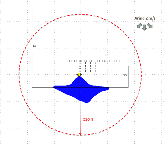
In these cases, an accurate determination of the exclusion zones is critical to determine the viability of a project. The screening calculations using PHAST rarely suffice for maintaining control in the exclusion zones. For example, a flashing and jetting release from a 2-inch hole in an LNG truck loading supply line at 40 psig will travel about 510 feet, which is likely to exceed the distance available in many satellite LNG facilities.
If the exclusion zones still extend offsite, passive mitigation measures can be implemented to further reduce the cloud migration and retain the ½-LFL vapor cloud onsite. The most common mitigation measures, due to their versatility, are vapor barriers:
• They can be placed in most locations (along the property line, close to the release location or anywhere in between) as long as they do not interfere with facility operations.
• They can be built in a variety of sizes and materials (plastic, metal, masonry) to accommodate site-specific vapor dispersion requirements. For example, adding slats to a facility’s security fence can, in some cases, provide sufficient flow restriction to keep the vapor dispersion exclusion zones onsite.
A comparison between the jetting and flashing vapor exclusion zones (Figure 1) predicted by PHAST and FLACS, which includes vapor barriers for a small-scale LNG liquefaction facility. The red-dotted circle represents the PHAST calculated ½-LFL distance, whereas the blue cloud represents the FLACS ½-LFL distance which is decreased due to the presence of a vapor barrier.
Other forms of mitigation to reduce the momentum and subsequent cloud distance from a jetting and flashing release can be pipe rack barriers, installing piping in trenches, or the use of shrouds or other deflective objects. In addition, good engineering practices during the preliminary plot plan development can locate the worst case spills away from the facility property line or position equipment to minimize piping lengths while meeting setback and spacing requirements to reduce vapor dispersion distances.
Conclusions
A fundamental requirement for the safe design of LNG facilities in the United States is that the public and public property be protected from credible accidents within the facility. The current regulatory requirements for facility siting can be significantly different, depending on whether a facility is under federal (PHMSA), state or local jurisdiction.
Therefore, one of the first steps in the planning of an LNG facility should be to determine applicable jurisdiction and performing a preliminary siting analysis in accordance with the jurisdictional requirements. This simple, yet critical, step will provide project developers with the level of confidence in the ability to site the project early on in the design phase before significant engineering and capital have been invested early on in the project.
Authors: Phil Suter is an LNG Consultant with over 10 years of experience in the LNG industry. Prior to working at CH•IV International, Suter worked for FERC in both the LNG Engineering and LNG Compliance Branches and worked on many LNG projects throughout the United States.
Jenna Wilson is an LNG Consultant at CH-IV International. She has been involved in the pretreatment, liquefaction, transportation, importation, storage and re-gasification processes of LNG, with specific focus on regulatory issues including facility siting, process design, hazard detection and fire safety, commissioning and compliance for LNG facilities.

Comments