
October 2014, Vol. 241, No. 10
Features
Corrosion Management Of Duplex Stainless Steel Gas Flowlines
The most commonly used materials for gas flowlines are carbon steel (CS) and duplex stainless steel (DSS). Selection of flowline materials should take into account the service for which the flowline is intended, the operating envelope and the life cycle costs (LCC).
For highly corrosive environments corrosion-resistant alloys (CRAs), in particular DSS, remains the most cost-effective option since the risk of corrosion failure on CS lines is high and use of corrosion inhibition with CS is often either impractical, costly or poses too high a risk.
However, DSS can still be susceptible to internal and external corrosion threats in both surface and buried environments. There are occasions where DSS can be degraded due to particular corrosion mechanisms that occur under certain operating conditions. As a consequence, corrosion management is as important for DSS as for conventional CS flowlines. The threat of corrosion can be effectively managed if DSS flowlines are operating within integrity operating window (IOW) and the material limits are clearly understood.
For these reasons, effective corrosion management of gas flowlines is one of the core requirements in maintaining the integrity of gas assets and extending their period of operation beyond their design life.
Materials For Gas Flowlines
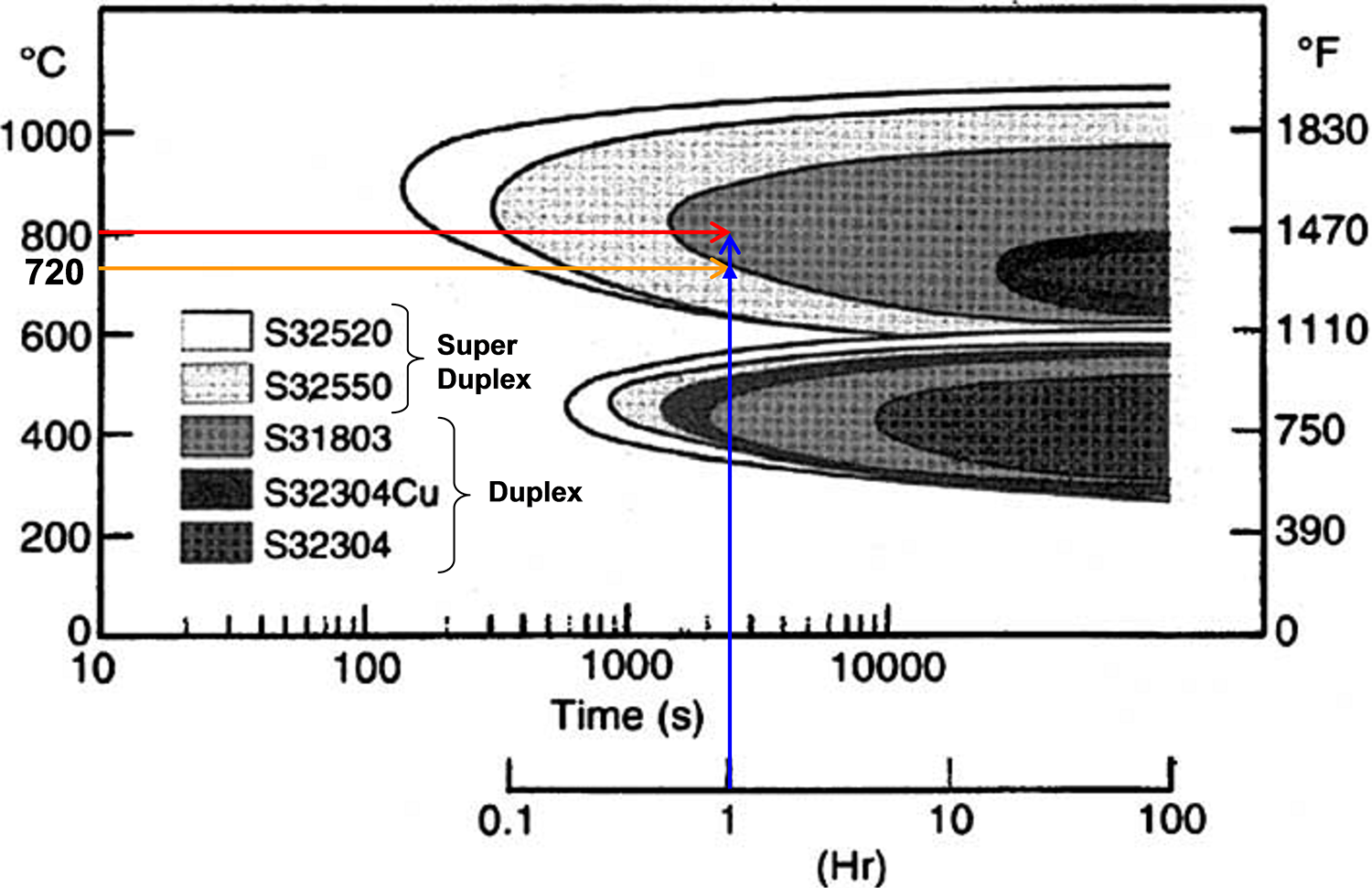
The DSS microstructure consists of approximately 50% austenite and 50% ferrite phases. However, if incorrectly heat-treated, these materials suffer from intermetallic phase (IP) precipitation, such as sigma and chi, that will degrade the mechanical and corrosion properties. The proportion of each phase depends on the exact composition and on the cooling rate during production or heat treatment (HT). It is highlighted in several studies that HT of DSS grades is critical since improper HT can deteriorate the beneficial properties that DSS offers compared to traditional austenitic grades.
Figure 1 Shows the time temperature transformation (TTT) of various DSS grades.
Though DSS is stronger, it does have some drawbacks with respect to welding. Conversely, it does have better corrosion resistance in chloride environments than the austenitic range. Welding controls must ensure that the weld deposit matches the ferrite/austenite ratio of the parent material; excess austenite will make the alloy weaker and excess ferrite will make the alloy more susceptible to hydrogen cracking.
Despite these shortcomings, the strength of these steels and the superior corrosion resistance make them a natural choice for pipelines where the corrosion resistance is paramount. DSS materials can perform satisfactorily in sweet sour and chloride environments.
DSS has excellent resistance to carbon dioxide (CO2) but the combination of hydrogen sulphide (H2S) and water-containing chlorides can lead to attack by crevice corrosion and stress corrosion cracking. Typical material for DSS flowlines generally is 22 Cr DSS grade, UNS 31803 with minimum nitrogen content 0.14%. Nitrogen requirement shall be considered as important for DSS grade as it contributes to corrosion resistance and phase balance of DSS grades.
Corrosion Management Of DSS Gas Production Flowlines
CRAs and specifically DSSs are generally not part of an inspection strategy and the specification of a CRA generally infers that a “fit and forget” philosophy has been adopted for that specific component. However, DSS can suffer from various degradation mechanisms, which will require an active corrosion-management strategy to be maintained.
The corrosion-management strategy for DSS flowlines should include five key components as shown in Figure 2.

Figure 2: Framework for successful corrosion management
Corrosion Risk Assessment
The precise data on the produced water composition within the flowlines is important to assess the level of risk to which the system is subjected. Internal corrosion can occur where the fluid has not been processed, for example H2S, CO2, organic acids or other corrosive components may be present in the line, which can, in the presence of water, cause rapid internal corrosion.
There are two major approaches to counteracting corrosion threats; the careful choice of material for the line and/or the use of chemical inhibition for CS to prevent the mechanisms taking place. CO2 internal corrosion is not a credible threat for DSS material as laboratory and operator’s experience shows that DSSs are resistant to CO2 corrosion even at very high partial pressures of CO2. In conditions containing H2S, the performance of DSSs are sensitive to chloride ions.
The main internal corrosion threats for DSS flowlines are: under deposit corrosion, stray current-induced internal corrosion of DSS isolating joints and, pitting and stress corrosion cracking.
Review of recent failures on DSS flowlines reveals that the failure morphology of in-service damage for DSS components is either stress corrosion cracking or pitting. Both these damage types occur with little warning and over a relatively short-time interval.
For internal inspection, ultrasonic testing (UT) tools should be equally as effective for DSS flowlines as they are for carbon steel. However, standard UT tools require a liquid environment to ensure adequate coupling between the sensors and the pipe wall. Before such tools could be used, gas flowlines would generally require decommissioning and then be water-filled. An alternative technique suitable for use in gas is the elastic wave tool which couples its sensors to the pipe wall via liquid-filled wheels. However, this is available for 600mm, 750mm and 900mm pipes only, i.e. the currently available sizes are too large for typical sizes of flowlines. Hence, inspection cannot be relied upon to detect cracking or pitting prior to failure.
External corrosion is less of an intrinsic materials problem and is normally mitigated by a combination of coatings and cathodic protection (CP). The main external corrosion threats for DSS flow lines are soil corrosion, chloride stress corrosion cracking (CSCC), stray current and cathodic interference and hydrogen-induced stress cracking.
Corrosion Mitigation Strategy
Primary means of external corrosion and CSCC mitigation is the use of coating systems which prevent corrosion by isolating the metal from the soil. The coating systems which are employed for the flowlines are:
• 3 LPP/3LPE – Three-layer polypropylene/polyethylene
• FBE – fusion bonded epoxy
• PE – polyethylene
In addition to coatings as the means of external corrosion mitigation, impressed current cathodic protection systems should be used for all lines to protect exposed metal where coating damage exists.
The flowlines should generally be protected by CP with transformers/rectifiers installed at the respective manifolds. The transition between above and below ground sections of pipe should be electrically isolated from the manifold by monolithic isolating joints made of DSS. The isolating joints should be internally coated using a solvent-free liquid epoxy or other compatible coating.
It is generally considered that if DSS is shifted to a more negative polarized potential than -850mV, with respect to a Cu/CuSO4 reference electrode, corrosion should be prevented. However, overprotection can be detrimental to the pipeline and may cause hydrogen embrittlement cracking to occur. It is recommended to set the CP protection level for all buried steel flow lines to be in the range -850 to -1150mV (with respect to Cu/CuSO4).
The metallurgy of the DSS family is complex and requires very close control of welding parameters if corrosion resistance is not to be adversely affected. Microstructure or phase balance of parent, heat-affected zone and weld metal should be between 35-60% ferrite. In addition, the formation of intermetallic phases such as sigma and chi phase and secondary austenite is a major risk during welding and markedly reduces both toughness and corrosion resistance. To produce the optimum mechanical properties and corrosion resistance, heat input and interpass temperature should be carefully controlled.
Corrosion Monitoring Strategy
Critical process variables should be monitored to ensure the flowline falls within the integrity operating window (IOW) of the flowlines. Process variables such as temperature, chloride content, oxygen and H2S should be monitored frequently for each well. Frequent fluid sampling is required to maintain the integrity of DSS flowlines. Changes in operating conditions and excursions beyond the IOW should be highlighted and assessed to ensure the flowlines are fit for purpose.
Coating integrity is verified principally by using the Direct Current Voltage Gradient (DCVG) technique for buried lines which can locate and size coating defects by measuring variations in voltage gradient in the soil. It is usually performed in conjunction with a Close Interval Potential Surveys (CIPS) survey. CIPS and DCVG are appropriate inspection techniques for buried flowlines with impressed current cathodic protection and are usually applied in tandem.
CIPS, which records the pipe-to-soil potential every 1 to 2 meters, indicates how efficiently the CP system is operating. The DCVG survey utilizes the pipeline’s existing CP system to accurately locate defects along the pipeline by measuring the voltage gradients in the soil caused by the flow of the CP current at these defects. The output of a DCVG survey usually contains a list of coating defects which are characterized as low/medium/high priority, depending on their size.
Soil-to-structure potential is a key measure of CP system performance. Therefore, the CP system performance is regularly verified using periodic CIPS surveys and frequent ON/OFF potential surveys. Operators generally record the ‘ON’ pipe-to-soil potential on a quarterly basis and the ‘ON and OFF’ potentials annually. CIPS surveys are carried out periodically, typically every five years, based on the external corrosion threat on the line.
Other parameters that are monitored include transformer rectifier station output voltages and currents, ground bed resistance, auxiliary drain currents, etc.
The CP system performance can highlight potential issues related to corrosion at isolating joints. There have been a number of incidents of corrosion at isolation joints with several contributing factors. The original coating was not thought to be suitable for the service conditions which required alternative materials to be identified.
Most inspection techniques have been directed toward prevention rather than detecting or monitoring the growth of the damage. Most operators carry out coating examination for pinholes, damage, degradation, etc. Review of operator’s strategy for inspection of DSS flowlines reveals a number of inspection techniques used by the operator.
The chief issue when mothballing/suspending a DSS pipeline/flowline will be pitting caused by the presence of chlorides, liquid water and air ingress. For localized corrosion to occur at ambient temperatures, liquid water, chlorides and oxygen all need to be present. Localized corrosion is promoted by the presence of deposits. Thus, the objective when suspending a pipeline/flowline must be to remove one or more of the factors that promote localized attack.
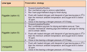
Table 1 shows two general strategies that can be used when preserving duplex lines and is split into piggable and non-piggable lines. The strategy attempts to minimize the use of water to avoid complex drying requirements and the potential for leaving water at low spots. An alternative in regions where low chloride potable water is available in abundance is that the line can be displaced with potable water as opposed to drying.
Table 1: DSS flowline preservation strategy
Corrosion KPI Scorecard
Reporting on key performance indicators (KPI) for the duplex flowlines should include status of CP test every month, coating integrity checks using CIPS/ DCVG every five years and fluid (including) chloride sampling analysis during well tests:
• Periodic KPI performance verification correlates inspection findings
• KPI checks confirm variance from defined values
Corrosion Data Management Reporting And Performance
The corrosion-management team receives a number of monthly reports on corrosion management activities and barrier status. The corrosion-control department should report on corrosion-management barrier status to the asset owners on a quarterly basis. A Pipeline Integrity Working Group (PIWG) should be established as the principal management forum for communication and discussion of the prevailing integrity issues and anomalies.
PWIG meetings should be held on a regular basis. The exact content will vary with issues arising but must include:
1. Review of all anomalies affecting SCEs (safety critical elements) and current status of repair (as applicable)
2. Review of all significant corrosion monitoring activities undertaken since the last PWIG meeting
3. Review of the updated corrosion management manual (CMM)
Any inspection anomaly or defect identified by the reporting process should be assessed and required corrective action taken as appropriate. Corrective actions including repair, further inspection or fabric maintenance should be entered into the database system as a notification.
Anomalies in corrective action and corrective action due dates should be listed and reviewed on a monthly basis with operations management. Any relevant anomaly information should be fed back into the corrosion-risk assessments for possible change in frequency, type and locations of inspections or monitoring activities.
Any material changes to the corrosion barriers should be subject to technical due diligence followed through by a management of change procedure and approved by senior corrosion professionals. Technical notes and reports should be published to record all details of the modification from concept to design to implementation and close-out.
Reports may be required on an ad-hoc basis e.g. in response to corrosion failures, root cause investigations, review and audits, etc. The reports should be maintained in a centralized database and the lessons learned incorporated in the integrity/inspection plans so that adjustment to corrosion-management strategy is reflected.
Conclusion
Although unique issues associated with welding, heat treatment, manufacturing QA/QC and inspections of DSS arise, these are not obstacles for successful use of DSS as a material for flowlines as long as an adequate inspection and corrosion-management strategy is in place.
There are circumstances where DSS can degrade, therefore, an inspection strategy with proper corrosion management is required, which means that some of the cost advantages in selecting CRAs are lost. Also, if the production data is poor or simply not available, (e.g. chloride and H2S level varies significantly across wells), then conservative assumptions may have to be made for a CRA design and subsequently, operating envelopes will need adjustment to make a CRA design choice more attractive.
Ultimately, the economic benefit of CRA steel production systems needs to be evaluated for each specific project, as the CAPEX of CRAs and carbon steel can vary widely, depending on external factors and project conditions.
Authors: Janardhan Rao Saithala is a Consultant in Materials & Corrosion with DNV GL and is based in Loughborough, UK. He has a Ph.D. in Corrosion from Sheffield Hallam University.
Tim Illson is a Senior Consultant in Materials & Corrosion with DNV GL. He has worked with the group and GL Noble Denton for 22 years combined. He has a Ph.D. in chemistry from Warwick University, UK and is a Chartered Chemist.
Angie Siddle is Senior Materials and Corrosion Engineer with DNV GL and has worked with the company for 22 years. She has a Ph.D. in Materials Science from Surrey University, UK and is a Chartered Engineer with IOM3.
Azrul Hilmi is an Integrity Management Consultant with DNV GL. He is a UK Chartered Engineer and has been involved in Corrosion & Integrity Management in the oil and gas sector for more than 15 years. Hilmi has a MSc in Welding Engineering from Cranfield University, UK.
Andrew Ramage is a Senior Consultant – Process & Integrity with DNV GL. He is based in Edinburgh, UK and has worked with the company for 37 years. Ramage has a BSc in Mechanical Engineering from Heriot Watt University, UK.
Ian Thompson is a Senior Consultant – Coatings and Cathodic Protection with DNV GL. Thompson has worked with the company for over 45 years and is based in Newcastle, UK. He holds a Ph.D. in Electrochemistry from Northumbria University, UK.

Comments