
July 2014, Vol. 241, No. 7
Features
Wet Gas Testing Using Custom Liquids, Magnetically Driven Centrifugal Pumps
Wet gas meter calibrations are usually done using natural gas, kerosene and water. Increasingly, gas producers are questioning a meter’s ability to measure wet gas entrained with the unique liquids found on platforms and wellheads (viscous hydrocarbons, paraffin based/high-wax liquids, sea water, brine solutions, MEG and other custom liquids).
Colorado Engineering Experimental Station, Inc. (CEESI) has recently added custom liquid testing capabilities to its wet gas facility, using versatile variable frequency drive (VFD)-controlled magnetic-drive centrifugal pumps.
Measuring Wet Gas
Gases from platforms and wellheads are often laden with liquids. Many produce a mixture of gas, liquid hydrocarbons (often called condensate) and free water. By volume, this wet gas mixture is mostly gas with small amounts of hydrocarbon liquids and water. Gas flow meters are principally designed for dry gas. When small amounts of liquids are present in a gas flow stream, large flow measurement errors often occur.
In the past two decades flow meter manufactures have worked hard to produce flow meters that are immune to measurement errors caused by liquids in a wet gas flow stream; their success has been limited. The search continues for a wet gas flow meter or combination of flow meters and technologies that can adequately measure wet gas over the wide range of flow rates and liquid loadings commonly found in the field.
While the search continues for the perfect wet gas meter, some progress has been made. Wet gas is being successfully measured by using a combination of technologies and flow calibrations. Successful wet gas meters typically require a calibration at a wet gas test facility (WGTF) where a surrogate hydrocarbon liquid and water are pumped into the gas flow stream. The flow meter is installed in a section of pipe flowing the wet gas mixture.
By measuring the liquid flow streams and the dry gas flow streams separately, the wet gas meter readings can be compared to the actual amount of gas and liquid flowing in the pipe. The meter’s recorded output is compared to the actual flow rates and adjustments are made to the meter’s readings.
The meter’s performance is characterized and software adjusts are made based on the wet gas calibration and several correlating parameters, including gas velocity, gas density, the liquid’s properties, liquid loading, flow pattern, the Reynolds number and the Lockhart-Martinelli number.
Need For Custom Liquids
While most wet gas meters can be successfully calibrated and characterized using water and surrogate hydrocarbon liquids, some technologies are influenced by the unique fluid properties at wellheads. For example, seawater and brine solutions can affect water detection capacitance readings.
Paraffin and high-wax content hydrocarbons have unusual surface tension properties that can influence flow patterns, the Reynolds number, emulsification formation and gas-liquid mixing relationships. Gas producers are now questioning the ability of meters to perform in field conditions based solely on water, surrogate hydrocarbon liquid calibrations and theoretical fluid property corrections.
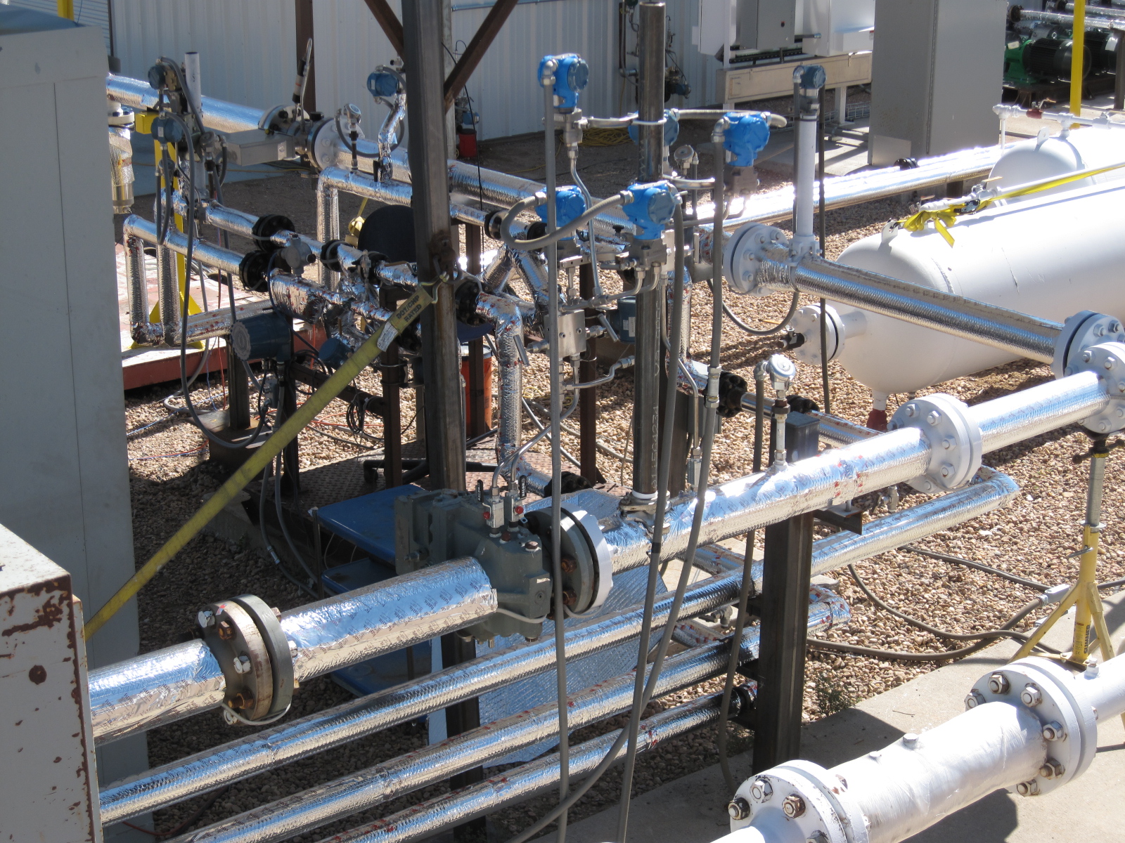
In 1999, CEESI set out to quantify two-phase flow measurement errors by building a wet gas test facility (WGTF). CEESI’s WGTF is a closed-loop system that circulates high-pressure natural gas in a loop and injects hydrocarbon liquids and water into the gas stream. The combined multiphase liquid and natural gas fluid travels past the meter being calibrated, called the meter under test (MUT).
By separately measuring the injected liquid flow rates and the dry natural gas flow rates before they combine, the over-registration/under-registration of the MUT can be accurately determined. CEESI’s facility uses a bank of liquid Coriolis meters, along with gas turbine and ultrasonic gas meters in series, to determine the individual liquid and gas flow rates.
While the engineering principles of a multiphase test facility are simple, the operation is complicated and involves gas-liquid separators, liquid-liquid separators, heat exchangers, chillers, charging and recirculating compressors, dozens of pressure and temperature measurements, real-time gas chromatography, and level and quasi-steady state balancing.
New Multi-Phase Demands
As the value of oil and gas increases, the need for lower uncertainty flow measurement increases. Gas companies are becoming increasingly concerned that the diverse liquids coming out of the ground from different gas formations cause flow measurement errors not captured by just mixing natural gas with water and immiscible hydrocarbons.
Gas formations contain varying amounts of aromatic hydrocarbons and paraffin-based condensate liquids. Offshore wells bring sea water and brine solutions to platforms and measurement locations. These various liquids have a wide range of densities, viscosities and fluid properties that can affect a flow meter’s performance in unpredictable ways.
High velocities and elevated turbulence levels can cause liquids to combine with different natural gas components to form emulsifications, a foamy mixture of gas and liquids. At lower temperatures, water molecules can combine with methane molecules to create hydrates – methane ice-snowballs that can plug pipes and shut down operations.
Custom Liquids In WGTF
To meet these demands, CEESI had to modify its facility. Injecting salt water, brine solutions, or waxy paraffin liquids into the existing facility would foul the piping and contaminate the next test setup. Building separate test facilities for the vast number of liquids was economically impossible.
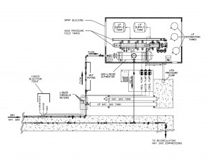
The solution was to build an additional adaptable test facility that could inject an array of liquids over a wide range of flow rates into the gas stream, and then capture the injected liquids immediately after the MUT. CEESI’s Custom Liquids Wet Gas Test Facility (CL-WGTF) was built and commissioned in 2013.
While many of the design and operational features of the CL-WGTF remain proprietary, the diagram below shows the general layout.
One of the biggest engineering challenges facing the CL-WGTF was moving the many and diverse liquids from pressurized holding tanks to the liquid injection site. The injecting liquids have densities ranging from 1.03 g/ml (sea water and brine solutions) to 0.74 g/ml light hydrocarbons (kerosene, Exxsol D-80). The viscosities range from 0.5 cP to 150 cP.
The flow rates need to be controlled from 0.5 gpm to 42 gpm with operating temperatures varying from 50° F to 125° F. Many of the liquids are flammable and toxic. Standard piston-style positive displacement pumps produce pulsations in the flow stream that can influence a flow meter’s performance. Electrical power availability and operational economic constraints limit pumping horsepower ranges.
Proper Pump Design
The solution was to use three magnetic-drive, centrifugal pumps for the low-flow, high-suction pressure (1,000 psi) application. The pump design included a high nickel alloy rear casing material for corrosion resistance and the high static pressure rating needed to minimize hysteresis losses. Custom high-torque inner and outer magnets were also used.

To further reduce power consumption and to control the flow rates over our wide operating range (0.5 to 42 gpm), programmable variable frequency drives (VFDs) were used. Maximum-diameter pump impellers were used, which resulted in higher efficiencies at the lower speeds and gave the facility greater flexibility in other applications requiring high flow rates and non-favorable specific gravities and viscosities. Maximum-diameter pump impellers provided a significant improvement over the original plan to use trimmed impellers with constant speed drives.
.")
Because the liquids being pumped have such a wide range of viscosities and lubricity, the pumps were supplied with special silicon carbide (SiC) bearings for protection during startup. Additionally the bearings incorporated a hydrodynamic bearing design in which the pumped liquid acts like a “cushion” (similar to car tires hydroplaning on wet pavement).
The seal-less design eliminated potential leak-path issues and provided an added level of safety for the flammable liquids. The pumps were supplied with close-coupled motors, eliminating alignment issues and making the footprint smaller.
The curve shows the theoretical pump performance for the initial liquids used in commissioning the CL-WGTF (water, mono-ethylene-glycol and hydrocarbon condensate).
The table illustrates the importance of properly calculating head for various fluids – failure to do so could mean the pump selected is not large enough. CEESI was pleasantly surprised that the pump supplier met its extremely tight delivery schedule and during the commissioning of the CL-WGTF all three pumps either met or exceeded the manufacturer’s predicted performance curves.
Lessons Learned
While this article discusses custom liquid wet gas testing, several lessons were learned in the building of the CL-WGTF that gas producers and processors should find valuable:
1. Spend the extra money on the critical components that drive your system. CEESI spent the extra money on quality pumps and VFD controllers and it paid big dividends in operating costs, long-term maintenance and safety.
2. Flush your system prior to startup and install witches hat strainers on the pump inlets. While CEESI installed 30-micron high-pressure filters and flushed all of the pressure vessels prior to startup, piping runs leading from the filters to the inlet of the pumps could not be flushed in situ. As Josh Kinney, WGTF operations director, said, “We installed witches hat strainers on the pump inlets and that saved our bacon. Unexpected weld slag and pipe rouge lodged in the witches hat strainers, which would have damaged our new pumps.”
3. Use a VFD to control pumps. If you operate over a wide flow range a programmable VFD controller is a must. It saves time and money in the long run. Pump bypass systems are more difficult to control and consume a lot more energy at lower flow rates.
4. Get your vendors onsite and have face-to-face meetings early in the design process. CEESI worked hard designing the CL-WGTF, but vendor input proved even more valuable early on in the design stage. CEESI had several onsite, face-to-face meetings with vendors that altered and improved the design of the CL-WGTF.
5. Use a pump supplier that has a lot of applications knowledge and is willing to take the time to understand your process and its challenges. CEESI learned a lot from its pump supplier. Understanding how a pump is integrated into an entire system is critical. The relationship between head, flow rate, horsepower required, motor rpm, efficiency and VFD control on a performance curve was the difference between success and failure. Having a supplier with the experience to size the right pump based your system requirements is key.
CEESI CL-WGTF Specifications
• Maximum pressure: 1,050 psi
• Operating temperature: 60-125°F
• Nat. Gas flow rates:
10-60 feet/sec (4-inch sch 80 pipe)
0.8-4.8 actual cubic feet/sec
• Hydrocarbon flow rates:
10-100 lbs./min
• Water/salt water/brine flow rates:
10-120 lbs./min
• MEG/methanol flow rates:
4-40 lbs./min
?
CEESI History
• The year was 1951: a gallon of gas cost 20 cents; Harry Truman was president; Mickey Mantle and Willie Mays were rookies and the University of Colorado’s Engineering Experiment Station (CEESI) was born.
• Originally a nonprofit organization, CEESI tested rockets for the U.S. Navy. In 1966, Professor Tom Arnberg, head of the Mechanical Engineering Department at CU, moved operations to a decommissioned Atlas E missile facility and began testing flow meters. Arnberg developed some of the first high-pressure gas flow standards in the world, including the critical flow venturi (CFV). Several CFVs developed during that time are still in use at CEESI.

• In 1986, CEESI reincorporated as a for-profit company, becoming the largest commercial flow test facility in North America testing both air and water.
• In 1999, CEESI added natural gas and multiphase fluids testing capabilities.
• In 2013, the single-pass multiphase wet gas test facility was commissioned using magnetic-drive centrifugal pumps to handle a wide range of fluids.
Authors: Eric Harman has been a project specialist and staff engineer at CEESI since 2008 and has worked in the flow measurement field for 33 years. He holds a bachelor’s degree in biochemical engineering from the University of Colorado. Harman can be reached at (970) 897-2711 or eharman@ceesi.com.
Mike Clark has been a sales and engineering manager at Magnatex Pumps, Inc. for nine years and been in the pump business for 37 years, including serving as one of Pipeline & Gas Journal’s first contributing editors. Clark holds a bachelor’s degree in engineering administration and can be reached at (713) 972-8666 or mclark@magnatexpumps.com

Comments