
December 2014, Vol. 241, No. 12
Features
Leak Detection Systems Critical To Pipeline Safety
Selecting a suitable leak detection system is not an easy task for pipeline operators. The system must meet the needs of the particular application and comply with relevant regulations. The most advanced technology available uses the extended real-time transient model (E-RTTM) model, which guarantees reliable leak monitoring for various types and lengths of pipelines, even under transient operating conditions.
Industry recommendations on system sensitivity, precision, robustness and reliability
The American Petroleum Institute (API) provides a detailed overview of recommended leak detection system requirements in API RP (Recommended Practice) 1130. The recommendations include general suggestions for operating leak detection systems as well as detailed performance criteria for selecting a leak detection system. The linked and interdependent criteria include:
Sensitivity – The system should detect even small leaks within a short period.
Precision – The system should locate leaks precisely, and should indicate leakage rate, the quantity of escaped product (leakage rate multiplied by time) and the product that is escaping.
Robustness – The leak detection system should continue active monitoring even in unsteady or non-ideal conditions, including temperature fluctuations, changes in viscosity and sensor failure. This includes unsteady operating conditions (transient operation), for example due to effects triggered by pumps or valves.
Reliability – The system should not generate false alarms, even though it is highly sensitive.
In addition to regulatory requirements, other characteristics that affect the choice of leak detection system may include technical and environmental parameters, such as the length of the pipeline, whether it runs above or below ground, and the volume, type and quantity of different products to be transported.
The desired type of monitoring may be considered: internal (using process measurements), or external systems, which are physically installed along the outside of the pipe and sound an alarm on any change of temperature or environment. These are generally only applied in small pipe sections, due to high cost and installation complexity.
Real-Time Transient Model
A variety of systems are available on the market. Internal systems are usually preferred, and there are several options based on different mathematical and physical principles. A real time transient model (RTTM) is the leading technology; the other significant method is volume or mass balancing, which effectively amounts to measuring what goes in and comparing it to what comes out.

This is somewhat effective, but only in steady state conditions. It does not work reliably in real-world situations in which pipelines are subject to variable fluids conditions, including density changes, varying line packing (pipes do not always stay completely full along their entire length), or other such transient states. In those cases, the balance systems can misinterpret normal situations as leaks, so false alarms are too common.
RTTM is a mathematical model that compares measurements taken during the actual operation of a pipeline with a computer simulation of the pipeline (called a “virtual pipeline”) in real time.
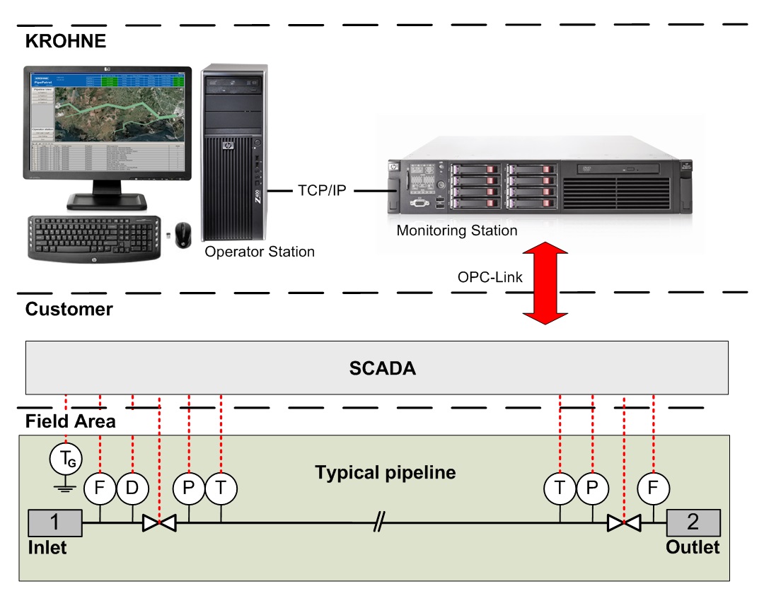
An E-RTTM leak detection system creates a virtual image of a pipeline based on real measured data. Measurement values from flow, temperature, and pressure sensors installed at the inlet and outlet of the pipeline and along the pipeline at pump and valve stations are crucial.
The flow, pressure, temperature and density at each point along the virtual pipeline are calculated from the measured pressure and temperature values. The model compares the calculated flow values with the actual values from the flow meters.
If the model detects a flow discrepancy, the leak signature analysis module determines whether it was caused by an instrument error, a gradual leak or a sudden leak.
When measured to the API RP 1130 performance criteria, the E-RTTM provides a high degree of sensitivity and quick leak detection with real-time comparison of existing measuring results against leak signatures, which are stored in a database. Comparison of measurement values with the leak signatures is also critical to reliability because it provides a high degree of protection from false alarms.
E-RTTM-based leak detection systems are able to handle changing or transient operating conditions that are not recognized by less sophisticated internal leak detection systems. An E-RTTM-based leak detection system works with dynamic values which also improves robustness. The system can adapt automatically and quickly to such changes in the operating conditions as sensor failure, communications failure, a valve closing or a product change in the pipeline.
The E-RTTM uses three different methods of identifying and pinpointing leaks: the gradient intersection method, the wave propagation method, and the extended wave propagation method. The leak detection system calculates the most probable leak locations by comparing the results of these methods, making it extremely precise.
The gradient intersection method (Figure 2) is based on the pressure profile of a pipeline. The occurrence of a leak changes the pressure gradient along the pipeline in characteristic manner.

Without a leak, the drop in pressure in a liquid pipeline is linear (blue line). When there is a leak, the pressure gradient changes and two linear segments appear with different slopes (orange). The leak position can be determined by calculating the intersection point.
The second option for leak identification is the wave propagation method (Figure 3), which analyzes the pressure waves that result from a leak. If a sufficiently large leak occurs suddenly, for example if the pipeline is damaged by an excavator, a negative pressure wave spreads at the speed of sound in both directions along the pipeline.

The leak position can be calculated by comparing the arrival time of the pressure wave at the pipeline inlet and outlet pressure sensors.
The extended wave propagation method is based on the same physical principle as the wave propagation method, but also takes into account additional values from pressure sensors installed in measuring and control stations along the pipeline, and speed of sound data for the current product. This enables more precise detection of the leak by reducing errors due to delayed sensor reaction or slow signal transfer. Figure 4 provides an illustration of the method.


Comments