
September 2013, Vol. 240 No. 9
Features
When Faster Doesnt Mean Better: Optimizing Inline Inspection Tool Velocity
Faster means better, most of the time. Faster gathering, faster processing, faster transmission. We all see the obvious benefits of getting and going faster. But faster isn’t always better.
There are things well worth the additional time and effort they require. This is certainly the case with inline inspection (ILI) in which slower optimal tool velocity typically means more accurate, robust and actionable data for pipeline operators. Getting to that optimal velocity, however, is more challenging than it may first appear.
Traditional, free-flowing and autonomous ILI equipment traversing natural gas pipelines can present operators and integrity management providers with a host of obstacles to successful tool passage, including short radius or mitered bends, multiple pipe diameters, launchers and receivers too short to accommodate traditional inspection vehicles, to name a few. To further complicate matters, natural gas is a compressible medium.
At lower pressures it becomes very difficult to manage ILI tool velocity, as a long, elastic column of compressible gas sits between the inspection tool and the primary flow control source (compressor station). The result is a sporadic stop-start motion of the tool, which will remain in place until the pressure behind it builds high enough to propel it forward, at high velocity.
The tool will continue to travel until the upstream gas column expands enough that differential pressure is no longer sufficient to overcome the tool’s drag. Now, mix low pressure with just one additional obstacle and a successful inspection will be extremely difficult to attain.
One of the most commonly employed technologies susceptible to velocity fluctuation is magnetic flux leakage (MFL) for metal loss inspection, which has an optimal velocity range of 4-7 mph – or 1.79-3.13 meters per second (m/s). Controlling the tool’s speed is critical to ensuring the necessary pipe wall “saturation” for an accurate assessment.
According to the 1999 edition of Magnetic Flux Leakage Technology For Natural Gas Pipeline Inspection by Bruce Nestleroth and Tom Bubenik, “All electrical systems, from car alternators to power generation stations, rely on the physical principle that a changing magnetic field passing by an electrical conductor will induce a current in the conductor.
An MFL tool moving down a pipeline represents a changing magnetic field, and the pipe is an electrical conductor. As a result, currents are induced in the pipe. Applied magnetization levels decrease as velocity increases,”[1] which means faster traveling tools produce lower resolution and less accurate findings (Figure 1).
Although low pressure can cause troublesome velocity fluctuations during an MFL inspection, higher line pressure causes the gas to be less compressible and more liquid-like, posing additional obstacles to successful inspection, should product flow be insufficient to ensure ideal tool velocity.
From 2007-09, large-diameter natural gas pipelines in the United States were constructed to move high volumes of gas from strategic locations, such as shale plays, to market. Flow in these lines can reach upward of 2.4 Bcf/d, which can translate to more than 35 mph (15.65 m/s), well above the optimal MFL velocity range.
Regardless of the high flow rate, operators must still perform integrity assessments to proactively mitigate risk and to properly maintain their assets. Traditionally, operators would reduce their flow rates to accommodate the MFL inspection tool, potentially disrupting the product feed to high-flow transmission lines further downstream. With reduced product flow comes the negative economic trickledown for all involved parties.
In this scenario, either the ILI service provider must run an inspection at too great a speed, unable to provide accurate and comprehensive survey results, or the operator is forced to reduce flow, costing everyone money for every minute that this occurs. This is clearly a position that no operator or ILI provider wants to be in.
To address challenges on both sides, ILI companies have developed speed-control technologies that allow natural gas to bypass across a tool, reducing its speed and allowing for optimal inspection velocity range without disrupting operator flow. The T.D. Williamson (TDW) contribution to the speed-control solution is detailed here, as is a recent operator application for a large diameter, high-flowing natural gas line.
Solution For High-Flow Inspection
To meet the breadth of operator needs – accounting for individual pipeline characteristics and conditions – TDW employs an array of ILI magnetizers. The focus is the floating magnet-style axial MFL for metal loss inspection, as it is the technology that accommodates speed-control implementation in high-flow natural gas lines.
 speed control inspection results. Natural gas flow (dark blue) vs. actual tool speed (light blue). Both units in mph.")
The floating-style magnetizer uses skid plates to transfer magnetism to the pipe wall. Rather than using a fixed sensor ring, sensors are mounted to the interior of each floating magnet “arm” (Figure 2), providing more consistent drag during an inspection. More consistent drag helps minimize the tool’s stop-start speed excursions in which a tool may accelerate beyond its optimal range. Due to its ability to expand and collapse up to 25% of the pipe’s outside diameter (OD), the floating-style magnetizer also creates abundant spacing for gas bypass (Figure 3).

TDW also employs a variety of geometry technologies to accompany MFL inspections, including high-resolution deformation (DEF). DEF uses tightly spaced direct measurement arms for pinpoint sizing accuracy of dents, ovalities and pipe expansions (Figure 4). It has a minimum detection and sizing tolerance of less than 1% of the pipe OD. As most operators require high-resolution geometry as part of the MFL inspection, DEF is a necessary platform component.

Although capable of producing highly valuable data, deformation tools are not configured to allow flow bypass. This being so, a third component must be added to the platform to reduce and ensure optimal inspection tool velocity – active speed control (Figure 5).

Active Speed Control
An ILI tool moves when force – created by differential pressure across the device – becomes greater than friction produced by the tool within the line. To lower tool speed within high-flow natural gas pipelines, the differential pressure across the inspection tool must be lowered. This is accomplished by actively allowing gas flow to bypass the tool (Figure 6). When maintained at the appropriate level, the bypass will keep the inspection tool in the optimum velocity range.

A speed-control module was developed by TDW for this purpose. The device is controlled by a system that actively monitors tool speed during an inspection. Should the inspection tool begin to travel outside the established parameters, the valve will automatically adjust to maintain a velocity within acceptable limits of the onboard technologies.
The optimal platform configuration for an ILI tool running in these high-flow gas lines includes speed-control technology, high-resolution deformation, floating magnetizer for high resolution metal loss inspection and XYZ mapping. The deformation technology, as mentioned, is not configured to allow bypass. To maintain unrestricted flow across the floating magnetizer and through the active bypass, the deformation technology is incorporated into the speed control unit itself. This configuration allows for all requisite technologies to be integrated on a single tool. It also keeps the entire platform to a minimal length, which benefits logistics, on-site handling and reduces overall tool drag (Figure 7).

Case Study – Boardwalk Pipeline Partners, LP
Boardwalk Pipeline Partners, LP provides gathering, processing, transportation and storage of natural gas and liquids. Boardwalk and its predecessors have been delivering natural gas to heat U.S. homes and fuel appliances since the 1930s. Boardwalk’s networks were designed and constructed in accordance with the pipeline safety standards established by industry experts and the Department of Transportation (DOT). In fact, safety is integral to every step of its process, from facility design and construction, to operation and integrity assessment.
In 2012, Boardwalk systems carried about 12% of the nation’s average daily consumption of natural gas. Through its subsidiaries, Boardwalk owns and operates about 14,410 miles (23,190 km) of interconnected natural gas pipelines, serving customers directly in 12 states and indirectly throughout the Northeast and Southeast via interconnections with unaffiliated pipelines (Figure 8).[2]

Early in 2012, as part of its integrity management program, Boardwalk requested an integrity inspection of a 42-inch, high-flow natural gas pipeline, totaling 68.99 miles (110 km) and extending from Vixen to Tallulah, LA. Boardwalk stipulated the inspection must be completed with a single run “multiple data set tool,” including high-resolution deformation (DEF), high-resolution MFL (GMFL) and XYZ mapping.
Deformation tools can typically inspect lines at a maximum velocity of about 10 mph (4.5 m/s), while MFL tools have a maximum speed of 7 mph (3 m/s). In this line, however, due to the high pressure and flow, the gas velocity was expected to exceed 20 mph (9 m/s), greatly reducing both technologies’ ability to provide accurate data.
To achieve acceptable tool velocity in this high-pressure line and under these stipulations, Boardwalk would typically be forced to reduce gas flows. Boardwalk, however, required the inspection to be conducted within the normal course of pipeline operations – meaning pressures and flows would not be lowered to accommodate the inspection.
High customer expectations, rigorous operating requirements and challenging, even limiting, line conditions created the ideal application for active speed control (SPC) technology. The addition of an SPC unit would provide flow bypass across the tool, allowing it to achieve and maintain optimal velocity, meeting all of Boardwalk’s criteria for a successful inspection.

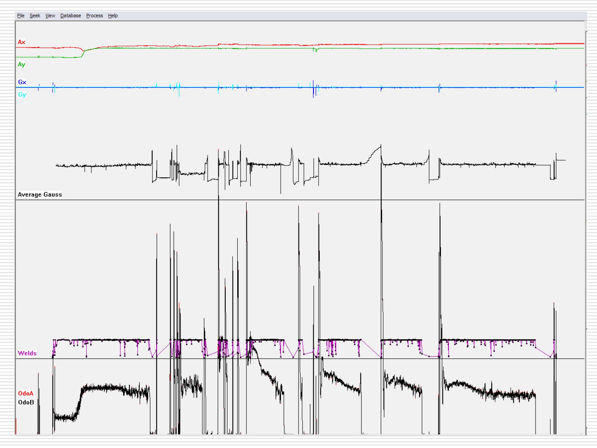
The inspection tool – SPC, DEF, GMFL and XYZ – was launched at the Vixen compressor station on Jan. 27, 2012 (Figure 9). It was tracked throughout the 68.99 mile (110 km), 13 hour-and-8-minute inspection to confirm its location and speed. Although gas flows during the inspection reached 20.32 mph (9.08 m/s) and never dropped below 16.97 mph (7.59 m/s), the addition of the SPC unit allowed the ILI tool to travel at an average of only 5.25 mph (2.35 m/s), well within the 4-7 mph (1.79-3.13 m/s) optimal velocity range. Even at such high pressure and velocity, the tool exhibited well-balanced dynamic performance (Figure 10).

Customization Saves Throughput, Money
Many pipelines around the world operate at conditions beyond the standard parameters of traditional inline inspection technologies, high-flow natural gas lines being just one example. These lines create additional challenges for gas operators who require integrity inspection with little to no impact on their transmission customers and the producers they support.
For Boardwalk, the value of providing inspection without a disruption in flow was clear. Without TDW’s active speed-control solution, flow would have been significantly reduced for the 13-hour duration of the inspection, as well as an additional hour to stabilize line flows. This would have meant a 14-hour reduction in throughput, with the end result being a drastic loss of revenues for both Boardwalk and its customers. Instead, Boardwalk was able to meet all of its project goals with no negative trickledown. As a result, Boardwalk fostered even stronger relationships with its own customers.
For forward-thinking operators, proper stewardship of assets is in ingrained in the culture. Companies such as Boardwalk are diligent to proactively address potential risks to their lines and disruptions to their customers. To do so, these companies look to pipeline service providers to deliver accurate, comprehensive and actionable integrity assessments. And, sometimes, it means slowing things down to do just that.
References and Acknowledgements:
1. J. B. Nestleroth and T.A. Bubenik. Magnetic Flux Leakage (MFL) Technology For Natural Gas Pipeline Inspection. MFL Topical Report, Gas Research Institute, February 1999.
2. www.BWPMLP.com
This article is based on the 2013 Rio Pipeline Conference Paper IBP1228_13 Use of Speed Control Technology To Enable Inline Inspection In High Flow Natural Gas Pipelines.

Comments