
March 2013, Vol. 240, No. 3
Features
Achieving Better Liquid Measurement Accuracy
Custody transfer measurement in the oil and gas business has been described many ways. It has been called, “An accuracy in measurement that both the buyers and sellers can agree upon” and “The best that can be achieved to meet the contract conditions.” But I prefer to call it, “The search for the truth.”
Ever since petroleum has been bought and sold, people have searched for better ways to measure oil and petroleum products on the fly with greater accuracy. One big advancement has been the pipe prover, which compares a known volume between two switches in a pipe to the meter reading. API requires an accuracy of the prover volume of 0.02% when compared to a standard such as NIST traceable Seraphin Cans.
If we want to put 0.02% accuracy into perspective, that is 6.45 teaspoons or a little more than two tablespoons of oil in a single 42 gallon barrel. That is very good measurement even at the worst case. We all strive to exceed the 0.02% required by API. We know and understand the value increased accuracy has to our companies. Today, prover water draws are repeatable to 0.001 and 0.002%
Accuracy of measurement is important when oil is selling at $100/bbl and profits are good, but it is even more important when oil is at $80/bbl and the margins are tight. One lost barrel becomes a much larger percentage of the profit.
When we are trying to implement a new and better method, we are burdened many times by company and industry standards and the old adage, “This is how we have always done it.” But sometimes, when we are faced with a problem, it needs to be solved outside the conventions. I say, “Necessity must become the mother of invention.” This is what is happening with bi-directional pipe provers.
By making the calibrated straight, repeatable detector switches, tipping the horizontal launchers, sizing the launchers properly and placing the pressure and temperature transmitters correctly, we are able to improve the bidirectional pipe prover. In some ways it is like the Alfred Hitchcock “Lamb to the Slaughter” TV episode of April 13, 1958. A wife kills her abusive chief of police husband with a frozen leg of lamb, then invites his detective friends for dinner and serves it to them. The famous line from the episode came from one of the detectives as they discussed the possible murder weapon at dinner. He said, “For all we know, it might be right under our very noses.” Better practices and methods can be like that, right under our very noses.
Are pressure and temperature transmitters really needed on the inlet and outlet of a prover?
For example, using the pressure transmitter’s published error span of ±0.15% of span at 100 psi the possible error would be 0.3 psi on just one transmitter. It takes 25 feet of pipe at full flow to cause a pressure drop of 0.3 psi. Would it be advisable to use two transmitters on 8-inch pipe, if the distance of the pipe between the meter transmitters and prover transmitter is less than 25 feet?
We used the following fairly typical flow conditions:
Flowrate (Q) = 2,000 Barrels Per Hour
Specific Gravity (S) = 0.88
Viscosity (?) = 10cP
Process temperature 700 F
Ambient temperature 900 F
The Velocity through an 8-inch ID line at the above conditions is 8.9 feet per second
From a pressure transmitter manufacturer’s data sheet we have the following:
Pressure transmitter data:
±0.15% of span
Span: 100 psi
100 x 0.003 = 0.3 PSI worst-case error per Transmitter
This from a pressure D-drop calculation:
It would take 25 feet of pipe at full flow to cause a pressure drop of 0.3 psi.
Query: Would it be advisable to use two transmitters if the distance of the pipe between them is less than 25 feet of 8-inch pipe?
On temperature, from the transmitter data we have a possible error of 0.02% of span on the 8-inch pipe at full 2,000 barrels per hour flow. Then using a span of -500 F to 2000 F the worst case error is 0.1450 C or 0.260 F. As above, the worse-case would be 0.520 F if one transmitter reads high and the other low. However, in this case we will split the error as above on the PT and use an error for one temperature transmitters of 0.260 F.
Temperature transmitter data:
– 0.02% of S-span
– Normal Span: -500 F to 2000 F = 2500 F
– Worst Case Error: 0.1450 C or 0.260 F
There are, of course, other variables such as wind and radiant heat from the sun. But under the above conditions it would take over 200 feet of pipe to cause a temperature drop of 0.260 F. If the process was 600 F and the outside ambient temperature was 800. Would it be advisable to use two transmitters if the distance of the pipe between them is less than 200 feet?
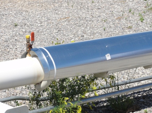
Minimize the radiant heat from the sun on pipe. The effect of radiant heat from the sun can be minimized with the use of a sun shade over the metering equipment. Or, as shown in the novel approach pictured, an aluminum cover is wrapped about 60% around the pipe with swimming pool vacuum hose was used as the spacer. At this installation, vaporization of the propane in the line was eliminated ensuring good measurement at the meter downstream of about 500 feet of this pipe. Insulation works also, but insulation works both ways; it can reduce the effect of radiant heat, but it can also trap heat in the process if the process is not flowing.
We tend to forget fluids are compressible in the piping between the meter and the prover. If the prover is a long distance from the meter, we need to take into account the compressibility of the fluid and the stretch of the metal in the pipe between the meter and prover due to the pressure. This includes the meter run and prover piping. In any distance, but especially in the longer distances, the fluid can compress as the prover sphere goes around an elbow or through a smaller flange opening, and then decompress in the straight pipe as the sphere reaches the detector. Changes in pressure of 1 or 2 psi are not uncommon. The effect is similar to what happens if air is trapped in the meter or prover piping while proving. This compression and decompression of the fluid can abort a prove.
Correction for the effect of pressure on the steel in the prover:
(Cpsp) Correction for the Pressure in the Steel of a prover including the piping:
Cpsp = 1 + (Pp x D) / (E x t)
Pp = Rounded average pressure in prover in PSIG. 1
D = Internal diameter of the prover pipe, in inches (outside diameter minus twice the wall thickness. Average ID 8
E= Modulus of elasticity (E = 30,000,000 for mild steel, E = 28,500,000 (for stainless steel)
t = Wall thickness of the prover pipe in inches. 0.375
Length of pipe 60 feet = a volume of 157 gallons
(1 + ((1 x 8) divided by 30,000,000)) x 60
1.0000003 x 60 = 60.000016 or an increase in volume of 0.000016 gallon
Correction for the effect of the pressure on the liquid in the prover:
Correction for the Pressure on the Liquid in the Prover = 1 / [1-(Pp x F)]
Pp = Rounded average pressure in the prover in psig
F = Compressibility factor for hydrocarbons. (Actual F values should be determined for each meter installation. If actual values are unknown, refer to tables in API Chapter 11.2.) = 1 / [1-(1 x .0000045)]
Length of pipe 60 feet =a volume of 157 gallons
1-0.0000045 = 0.9999955 x 157 gallons = 156.9992935
157 – 156.9992935 = 0.0007 gallon or .5376 teaspoon which is a good portion of the max 0.02% or 2 tablespoons per barrel allowed.
Different fluids have a greater or lesser compressibility, but it does have an effect on proving? The above case is also based on 100% stable crude. Who has that? Therefore the shorter the distance between the meter and the prover the better.
API recommends the length of the pre-run of the prover to be one half the cycle time of the four-way valve, times the velocity of the sphere, times a safety factor of 1.25 feet. But, the sphere does not have the same velocity from the beginning to the end of the four-way cycle. The sphere comes to a complete stop when the four-way is open and remains in the open position as the valve changes direction, before it starts to seat. Therefore, there is an average velocity from stop to full flow in each direction. Plus during the time the four-way is full open the sphere does not move at all. Unfortunately, these flows and no flows are not published information from the four-way manufacturer. If this information was available, a lot of money could be saved on the pre-run pipe and the space the provers need on site.
Detector Switches
There are several manufacturers of sphere detector switches. All are very good. The API document Manual of Petroleum Standards Chapter 4-Proving Systems Section 2 – Displacement Provers Appendix A – Analysis of sphere position repeatability gives a mathematical explanation of sphere position repeatability. Naturally, the rounder the ball the more precise the detector contact will be. Detector switches are normally repeatable to within 0.002 inch. However, the repeatability of switch and the required volume are not the only things that affect the volume of the calibrated section.
Prover Sphere

Reducing Pipe Contact
By reducing the inflation on the sphere, the spheres will have less distortion. They will last longer and the prover does not have to be opened to replace or check the sphere as often. Unfortunately, the elbows in the U-shaped prover require more inflation to ensure the sphere seals against the rover piping as it passes through the elbows and flanges.
The less the sphere has to be inflated, the less chance the sphere has to distort or wear as it moves through the pipe. And, of course, it causes less pressure drop. It takes approximately 80 psi to inflate a 30-inch sphere to 3% oversize. And 6% over inflation it is almost 200 psi of pressure inside the sphere. If the same sphere is inflated to 1%, only 30 psi is required. Less pressure in the sphere means less stress on the ball and less friction as the sphere passes through the prover pipe. Friction between the sphere and the pipe causes wear. One percent over size gives over a 4-inch-wide contact area on the pipe using a 30-inch sphere; this is more than enough contact area to ensure a good seal for straight smooth pipe.
There are several very good prover ball sphere manufacturers. All make spheres suitable for provers in custody transfer service. To optimize the life and condition of the sphere as it comes in contact and trips the detector switch, it must be selected and sized properly. Different materials such as urethane and polyurethane with polyurethane are the most popular. The yellow prover ball with a hardness or durometer of 55 is well-suited for crude oil and many refined products such as LPG and LNG.
The green sphere with a durometer of 65 is best suited for MTBE, benzene and solvents. The red prover ball with a durometer of 75 is best suited for chemicals such as toluene and propylene. The neoprene sphere is a softer general purpose sphere. But it does not have the wear capabilities of polyurethane. Spheres are also available impregnated with Teflon and other materials to give them less resistance to drag and make them move smoother when proving non lubricating fluids.
Better Reliability
Wear and tear on equipment is caused by the stress put on the equipment, less stress, less wear. Reducing the drag on the prover sphere as it moves through the prover reduces the wear on the ball and the coating inside the prover. That means longer ball life and longer prover barrel life requiring less maintenance and repair.
Sphere Storage
Prover spheres should be stored so they do not distort or get flat spots. Placing the sphere in a burlap bag and hanging it is a cool dry location is a good way to store the sphere. This prevents flat spots on the ball and damage that could occur if the sphere is stored on a warehouse shelf. The burlap distributes the weight of the sphere and keeps moisture away from the sphere. Spheres can also be placed in a bed of sand where the sand provides uniform support.
Sphere Launching Chambers
Building the launchers so the spheres are not damaged when they enter the launchers also reduces the number of times the prover needs to be opened to check or replace a damaged sphere. By placing different size spheres in the PVC test apparatus shown, the action of the ball could be observed. At velocities around the ball of over 5 feet per second, the spheres were carried rapidly into the discharge regardless of whether the pipe was placed vertical or horizontal. When the velocity was less than 5 feet per second, the sphere did not rise in the vertical launcher and moved more slowly down the horizontal piping. If the discharge of the launcher was in the upward position, the spheres were not pulled into the discharge. The velocity of the fluid around the sphere is easy to calculate and shows that two pipe diameters larger than the prover piping does not work in all cases especially the larger sizes.

Launching chambers can be either horizontal or vertical, and each has its advantages and disadvantages. A huge disadvantage of a horizontal launching chamber is the ramp in the launchers to keep the sphere close to the prover pipe so it will launch. If it is too close to the opening, the sphere will be lifted and fluid will pass under the sphere; if the ramp is too far back the sphere may not be close enough to the opening to launch.
The horizontal launcher also has to be perfectly horizontal so no air is trapped on one end of the launcher. And the prover has to be completely drained for sphere removal and maintenance. By tipping the entire launching chamber 20, the angle of a typical ramp, these disadvantages are avoided.
The launcher can be tipped where the launcher connects to the pre-run, or it can be tipped by rotating an elbows a the return bend, to any angle required. When the launcher is tipped, no ramp to launch the sphere is required and the ball launches easily because both the reducer and launcher are tipped and the ball always comes to rest seated in the reducer to the calibrated section. The vent for the blind flange side can be placed in the top of the blind where the flange opening contacts the flange.

On the quick opening closure side some manufacturers will locate the vent of their closure at the top of the closure.
Quick Opening Closures
Each of the different quick opening closures has its plusses and minuses. In any case the closure should have a safety that prevents the closure from opening when there is pressure in the launching chamber. If a closure is tipped more than 50, there should be an equal angle at the closure connection to return the closure to a horizontal orientation. Tipping a launcher over 50 makes it difficult to remove and replace the closures because they are only designed for either vertical or horizontal applications.

Installing reducers on the launchers where the piping from the four-way is attached to the launcher increases the pipe size into and out of the launchers and lowers the pressure drop caused by the bars or other protection placed in the launchers to keep the ball from being pulled into the four-way piping.
Development Of The WFMS SCS Prover
Finding good elbows to go in the calibrated section, especially in the larger sizes, has become difficult. To avoid this problem WMFS designed a prover with a straight calibrated section. On the first SCS Provers, we had no idea of how much the repeatability would improve or how it would lead to other improvements like no machined flanges, easier maintenance, less sphere wear, or being able to easily tip the launchers. We only wanted to solve the fluid by passing the sphere in the elbows problem.

There are no alignment flanges in the calibrated section. Alignment flanges are expensive and machining on the flange or installing pins reduces the integrity of the alignment flange and therefore the piping system. Flanges in the pre-run are aligned using shoulder bolts that are approximately the same diameter as the flange bolt holes. Not having to cut or drill a flange is a safety improvement.
Elbows in the calibrated section cause a pressure and flow change as the ball moves through the elbow, and there can be loss of fluid if the elbow is not perfectly formed in the inside diameter. Because the ball does not have to go through elbows as it passes from switch to switch, less inflation of the ball is required making for better water draws and better proves with less pressure drop. On the SCS Prover there are no elbows in the calibrated section.
On the SCS Prover, the calibrated section can be rolled out and inspected without another water draw because no flanges are broken in the calibrated section. Additionally, the return elbows at the end of the calibrated section can be removed. By removing the ends of the prover the calibrated section is not disturbed. This is a cost savings both in time and water draw cost.
The SCS Prover is ideal for Coriolis and ultrasonic liquid meters with manufactured pulses. The flow before and in the calibrated section is not disrupted by the ball passing through elbows, welds or flange sets. And because the ball can be inflated less, it passes smoother, with less pressure drop, between the detectors.
Since the flow through the calibrated section is smooth the pulses from conventional PD and turbines will be more evenly spaced during the spheres travel through the calibrated section giving better proves, especially when pulse interpolation is used.
The sphere does not have to be over-inflated to compensate for irregularities in elbows and flanges; the higher the inflation of the sphere, the higher the drag on the pipe walls, increasing wear on the sphere and increasing pressure drop.
Water draw repeatabilities of 0.005% and better are common with the straight calibrated section prover. This of course also reduces overall uncertainty.
Proving Coriolis And Ultrasonic Meters
On Coriolis and ultrasonic meters, when the flow rate between the detector switches is constant, much better repeatability can be achieved. Removing the elbows from the calibrated section where the sphere must move through two different radiuses, or radii, with a skipping action, will improve the proving repeatability. Eliminating welds and flanges where the IDs can be slightly different also improves the repeatability.
Custody transfer measurement is still relatively new, and there is still much room for improvements to the existing technology. But just because we have not done it like this before, is no reason for not looking to improve any technology.
References
API Manual of Petroleum Measurement Standards Chapter 4—Proving Systems Section 2—Displacement Provers
API Manual of Petroleum Measurement Standards Chapter 8-Sampling Section 2-Standard Practice for Automatic Sampling of Liquid Petroleum and Petroleum Products
API Manual of Petroleum Measurement Standards, Chapter 4, Section 6, Pulse Interpolation.
API RP 14 E Recommended Practice for Design and Installation of Offshore Production and Platform Piping Systems
Temperature calculations Adam Hawley Research Engineer Fluid Dynamics and Multiphase Flow Section Southwest Research Institute
CEESI Measurement Conference Colorado Springs, CO, June 2012 by Daniel J. Rudroff, WFMS Inc. “Achieving Better Liquid Measurement Accuracy Using a Slightly Different Perspective”

Comments