
June 2013, Vol. 240, No. 6
Features
Surge Prevention In Centrifugal Compression Systems
Centrifugal compressor surge and its prevention have drawn significant attention in compressor literature and editorial content. An important aspect of surge avoidance lies in the design of the compressor station and, in particular, the piping upstream and downstream of the compressor.
Most anti-surge systems are perfectly capable of avoiding surge during normal operating conditions. However, unplanned emergency shutdowns present a significant challenge, and surge avoidance in these cases depends to a large degree on the station layout, in particular, the volume of the piping system downstream of the compressor.1, 2 Furthermore, the concepts used in the an-ti-surge system (valves, piping, coolers) also affect the start-up of the station, or of individual units of the station.
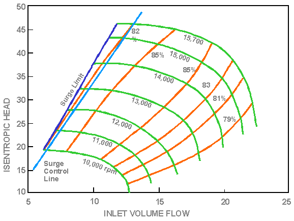
The possible operating points of a centrifugal gas compressor are limited by maximum and minimum operating speed, maximum available power, choke flow and stability (surge) limit (Figure 1). Surge, which is the flow reversal within the compressor, accompanied by high-fluctuating load on the compressor bearings, has to be avoided to protect the compressor.
The usual method for surge avoidance (“anti-surge-control”) consists of a recycle loop that can be activated by a fast-acting valve (“anti-surge valve”) when the control system detects that the compressor approaches its surge limit (Figure 2). Typical control systems use suction and discharge pressures and temperatures, together with the flow through the compressor, to calculate the relative distance (“turndown”) of the present operating point to the predicted or measured surge line of the compressor. The turndown is defined by:

If the turndown reaches a preset value (often 10%), the anti-surge valve starts to open, thereby reducing the pressure ratio of the compressor and increasing the flow through the compressor. The situation is complicated by the fact that the surge valve also has to be capable of precisely controlling flow. Additionally, some manufacturers place limits on how far into choke (or overload) they allow their compressors to operate.
As part of the control system, the anti-surge system has to fulfill three tasks:
• allow the starting and stopping of the compressor
• keep the compressor out of surge during changes in process
• keep the compressor out of surge during emergency shutdowns (ESD).
Putting it differently, the surge-control system must protect the compressor and the process. Therefore, it must do its tasks without causing fluctuations or disruptions of the process. Task 2 requires a valve that can be precisely controlled so that neither opening the valve nor closing the valve upsets the process. In a well-designed system, the compressor can operate from maximum flow all the way down to no station flow at all. This also requires a well-designed control algorithm.

Figure 2: Anti-surge and recycle system.
The design of the anti-surge and recycle system also impacts the start-up of the station (Task 1). Particular attention has to be given to the capability to start up the station without having to abort the start due to situations in which the allowable operating conditions are exceeded. Problems may arise from the compressor spending a certain amount of time recycling gas, until sufficient discharge pressure is produced to open the discharge check valve (Figure 3), and gas begins flowing into the pipeline.
Virtually all of the mechanical energy absorbed by the compressor is converted into heat in the discharged gas. In an uncooled recycle system, this heat is recycled into the compressor suction, and then more energy is added to it. Low-pressure ratio compressors often do not require after-coolers. There are three primary strategies that can be employed to avoid overheating the un-cooled compressor during start-up:
• accelerate quickly
• delay hot gas re-entering the compressor
• throttled recycle
If after-coolers are used, the heat from recycling can be removed effectively. However, a cooler in the recycle loop increases the volume of the system. As we will see, this affects the dynamic behavior of the system – for example, during emergency shutdowns.
A very critical situation arises upon emergency shutdown, Task 3. Here, the fuel supply to the gas turbine driver is cut off instantly, thus eliminating the power to the driven compressor.1 The inertia of compressor, coupling and power turbine balance the compressor absorbed power, caus-ing a rapid deceleration. Because the head-making capability of the compressor is reduced by the square of its running speed, while the pressure ratio across the machine is imposed by the up-stream and downstream piping system, the compressor will surge if the surge valve cannot provide fast relief of the pressure.
The deceleration of the compressor as a result of inertia and dissipation are decisive factors. The speed at which the pressure can be relieved not only depends on the reaction time of the valve, but also on the time constants imposed by the piping system. The transient behavior of the piping system depends largely on the volumes of gas enclosed by the various components of the piping system, which may include the piping itself, various scrubbers, knockout drums and coolers.
With the initiation of a shutdown, the compressor can be expected to decelerate by about 30% in the first second. With a 30% loss in speed, the head the compressor can develop at its surge limit will drop by about 50%. The recycle control valve must, therefore, reduce the pressure ratio across the compressor by one-half in that first second to avoid surge.
The system boundaries to study the ESD behavior are the first downstream check valve, while the upstream boundary may be either a check valve or an infinite plenum (at constant pressure, Figure 2).
Surge control systems must be sized to meet two diverse objectives: During steady-state recy-cling, the required capacity of the recycle valve can be directly derived from the compressor map: the smaller the valve, the smoother the control. During transient conditions, the required capacity increases due to the volumes on either side of the compressor. Therefore, to avoid surge during a shutdown, the bigger the valve, the better. To facilitate both smooth throttling at partial recycle and the need to reduce the pressure differential (DP) across the compressor quickly during a shutdown, control valves with an equal percentage characteristic are recommended.
With an equal percentage characteristic, the more the valve is opened, the greater the increase in flow for the same travel. We recommend two types of valves for surge control: globe valves and noise-attenuating ball valves.

Figure 3: The matching of the valve and compressor. The valve characteristic for a number of opening positions (60%, 70% and 100%) is superimposed to the compressor performance map.
In some cases, a solution using a single valve will not allow both a smooth process control and the protection of the compressor during emergency shutdowns. In this case, it may be necessary to either separate the tasks by installing a valve to handle emergency shutdowns (“hot bypass valve”) and a separate valve for process control (“recycle valve”). Different options are shown in Figure 4.
The recycle valve ideally would include the after-cooler in the recycle loop, allowing extended recycling without the risk of exceeding allowable gas temperatures. The hot bypass line would seek the shortest connection between compressor discharge and compressor suction. This would only be activated for emergency shutdown.
 (a
(a
 (b
(b
Figure 4: Anti-surge and recycle system: a) hot and cold recycle valve arrangement, b) parallel recycle valves.
Other options include the use of parallel valves (Figure 4b) in which two identical, parallel valves are used. For process control, only one of the valves would be used, while the capacity of both valves is employed during emergency shutdowns.
For a given compressor or compressor arrangement, the following questions have to be answered:
• What valve size is needed?
• How many valves are needed?
Surge control valves are primarily sized to fit the compressor (Task 2). During steady-state recy-cling, the required capacity of the recycle valve can be directly derived from the compressor map. To handle transient conditions, the required capacity must be greater to allow for the volumes on either side of the compressor.
The following guidelines pertain to a typical one valve, one compressor arrangement. More complex systems of cascaded valves or valves around multiple compressors require a more de-tailed analysis.
While the valve-sizing for Task 2 essentially requires matching the valve with the steady state compressor map, the evaluation of the system behavior in an emergency shutdown requires an assessment of the dynamic behavior of the system. While it is possible to perform a CFD simula-tion of an entire plant, and there are numerous instances in which that has been done, simpler methods are available.
There are also practical reasons. In general, during the planning stage, the exact plant geometry may not be known. If the valves are sized late in the project execution, they may become the pacing item in the project execution. Usually, the compressor performance maps, as well as the train inertia, are known early in the project. Although the compressor maps are strictly for steady state conditions, Blieske, et al,3 have shown that they are reasonably accurate for the problem at hand. (The key cause for deviations is in heat transfer and heat storage in the compressor, which is not included in the maps). As mentioned earlier, the control valve is sized based on process control needs. The unknown is usually the piping geometry.
Botros and Ganesan4 have analyzed a significant number of stations, and have established a pa-rameter, the inertia number NI, which is intended to determine whether a system will likely exhibit unstable behavior; that is, whether the recycle valve is sized correctly:

NI considers the rotor inertia J, the compressor speed N, the fluid energy transferred between the train and the gas, approximated by mass flow W and head H at surge, and the delay time of the recycle valve tdelay. They recommend that if the inertia number NI is less than 30, a shorter recycle loop with less volume would be needed, while if it is higher than 100, the current system is acceptable. More detailed review is recommended for NI between 30 and 100.
Another set of methods is described by Kurz and White 2. Here, simplified differential equations are solved that describe the dynamics of the system. They describe a model that includes the compressor map, the compressor inertia, as well as the system volumes.
From this complete model, some simplifications can be derived based on the type of questions that need to be answered. Obviously, for relatively short pipes, with limited volume (such as the systems desired for recycle lines), the pressure at the valve and the pressure at compressor dis-charge will not be considerably different. For situations like this, the heat transfer can also be neglected. The set of equations then is reduced to:

This means that the change in discharge pressure p2 depends on the capability of the valve to re-lease flow Qv at a higher rate than the flow Q coming from the compressor (Figure 5). It also shows that the pressure reduction for a given valve will be slower for larger pipe volumes (V). With the known behavior of the discharge pressure imposed on the compressor, the operating points of the compressor can be traced on the compressor map, and it can be determined whether surge would occur.

Figure 5: Simplified system and transient characteristic.
Both the methods described in Botros, et al,4 and Kurz, et al,2 are simple enough to use in re-verse: Rather than prescribing the piping geometry (or volume), they allow to calculate what the maximum allowable piping volume might be. If the piping design then exceeds this volume, a second, hot bypass valve might be necessary.
A properly designed anti-surge control system will reliably keep the compressor form surging, while allowing smooth process control. Simplified methods allow assessment of the system behavior in the planning phase, but the user has to be aware of the limitations due to the simplifying assumptions. This article provides some insight in the considerations when designing these systems.
References
1. Brun, K., Nored, M., 2007, “Application Guideline for Centrifugal Compressor Surge Control Systems,” Gas Machinery Research Council.
2. Kurz, R., White, R.C., 2004, “Surge Avoidance in Gas Compression Systems,” TransASME JTurbo Vol.126, pp.501-506.
3. Blieske,M., Kurz, R., Garcia-Hernadez,A., Brun, K.,2010, “Centrifugal Compressors During Fast Transients,” ASME Paper GT2010-22023.
4. Botros, K. K., Ganesan, S. T., 2008, “Dynamic Instabilities in Industrial Compression
Systems With Centrifugal Compressors,” Turbomachinery Symposium, Houston, TX.

Comments