
September 2012, Vol. 239 No. 9
Features
The Design of Natural Gas Pipelines

The modern pipeline design engineer must take into consideration many new factors – for instance, the federal Gas Pipeline Safety Rules, 49CFR Parts 191, 192 and 193. These include requirements such as maximum spacing for mainline shut-off valves, heavier wall thickness in populated areas and some design at 50% of SMYS (specified minimum yield strength).
Most states have their own pipeline safety rules which can be more stringent than the federal rules. In addition, there are EPA regulations that are necessary to be complied with such as an environmental impact statement for the entire system, limits on exhaust emissions, right-of-way screening before excavation, etc. Your final design must comply with all such regulations.
A good pipeline design should be a compromise between the cost of pipe in the ground and the cost of all the compressor stations. As a general rule, pipe in the ground is cheaper than compressors. Costs should be obtained from the pipe mills and from compressor engine builders and gas turbine suppliers. A computer program can be used to compare the overall costs of the entire system. The natural gas pipeline industry is still expanding and improving. Stronger steels, larger pipes and more electronic controls are all in the offing and will challenge future designers.
Route Selection
A major pipeline will probably have several points of gas production where natural gas is to enter the system. A gathering system may be needed to bring it all to a common point. If the gas contains a lot of liquids, an LPG stripping plant may be required as may a desulfurization plant. In any event, a starting and stopping point for the mainline must be determined. The route of the mainline must now be chosen. A straight line drawn on a map connecting the two points is a good way to start.
Then fly the line in a chopper and avoid as many problem areas as possible. Such areas might be subdivisions, schools, churches and other places of public assembly. Natural obstacles such as rivers, lakes, canyons, etc., should be avoided. In some cases, it may be necessary to go through a subdivision. Federal rules require that the wall thickness of the mainline pipe be such that the steel will not be stressed more than 50% of its SMYS.
SMYS is defined as the point at which the steel begins to stretch when under strain. This value is determined for pipeline steels by placing a small sample of the steel to be used in a machine which attempts to pull it apart and measures the strain imposed and also the length of the sample. The strain at which the sample begins to stretch (yield) is its minimum yield strength, usually expressed in pounds per square inch (psi). The purchaser of the pipe specifies the SMYS when he orders the pipe. For example, in X grades of pipe SMYS X70 means 70,000 psi SMYS, X60 means 60,000.
Another factor in route selection is the width of the right-of-way. For most lines, a permanent width of 50 feet is sufficient; however, during construction, a wider right-of-way may be temporarily needed. If future plans call for looping, a wider right-of-way should be purchased for the original line.
After the route has been selected, aerial photographs should be taken and a house count done for every mile of right-of-way at a width of 660 feet on either side of the line. See sketches marked as Appendix A.
The class location (Part 192.5 of CFR49) is then determined by counting the houses. For each mile of pipe within the strip of 1,320 feet (660 on either side of the line) the class location is as follows:
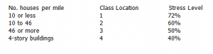
50% stress level is also required for special locations such as:
Offshore
Station yards
Within 300 feet of any building with human occupancy of 20 or more such as playgrounds, recreation areas, outdoor theaters, or any place of public assembly.
The design pressure equation for steel pipe is:
P =2stf over D
where P= pressure in psig
s= SMYS
D= nominal outside diameter of pipe in inches
t = nominal wall thickness in inches
F = stress level factor

These are standard wall thicknesses available from pipe mills. Non-standard thicknesses can be obtained but require special orders and prices. Having determined the miles of each wall thickness needed, bids may now be taken from qualified pipe mills which will supply the pipe. The pipe should go to a coating mill before being shipped to the job site.
Coatings for buried pipelines have been vastly improved. Plastic enamel-type powder sprayed onto a pipe heated to more than 400 degrees F gives an impervious glass smooth coat which prevents corrosion of the outer wall. If this same smooth coating is applied to the inner wall it will reduce the friction factor and result in a larger gas flow for the same pressure drop. Furthermore, this internal coating can be applied at the same time as the external coating while the pipe is hot.
Pipe
The maximum allowable operating pressure (MAOP) must now be determined. Obviously, the higher the pressure, the more gas you can pump. However, valves, fittings and compressors may not be available for higher pressures: 1,000 psig equipment is available whereas 1,200 psig may not be. Check with the suppliers of these items. The grade of steel must also be decided. X70 is being used throughout the industry; X80 has been used in a test section, but its use may create welding problems and it may not be available in large quantities.
Next, the pipe diameter must be chosen. Here again, the bigger the pipe, the more gas it will move. However, the same precaution should be used: 48-inch valves are available, but fittings, especially for 50% stress level, may not be.
Now we need to know the quantity of gas to be moved. For example, assume a quantity of 900,000 Mcf/d to be moved through a 30-inch pipe, MAOP of 1,000 psig. Try a station spacing of 60 miles. A modified flow formula (good for methane only) to determine the pressure drop between compressor stations is as follows:
P1-P2 = 2720FLgQ over D to the fifth power
where:
P1 = station discharge pressure
P2= next station suction pressure
g = specific gravity
Q=quantity in Mcf/d
D = diameter, inside
For the example used above:
L =60 miles
F = 0.012 (for slick walls)
Q = 900,000 Mcf/d
D = 29 in.
g=0.61

A compression ratio of 1.364 is a good one for centrifugal compressors driven by gas turbines. Therefore, the 60-mile station spacing is reasonable. If higher compression ratios are needed, then piston-type compressors should be considered.
?
Compressors
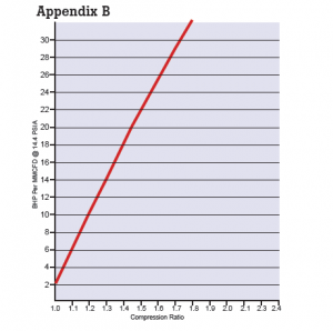
Curves of brake horsepower per MMcf/d of gas compressed are available. Such a curve is shown in Appendix B. For the example just used above, 8.15 brake horsepower per Mcf/d is required for a compression ratio of 1.364. A single gas turbine driving a centrifugal compressor rated at 8,000 horsepower is available, or two gas-fired piston-type engines rated at 4,000 BHP each are available.
Changes in gas supply and inlet pressure are likely to occur at the first mainline compressor station as well as at the last compressor station. Piston-type compressors can handle such changes more easily than centrifugals; therefore, it would be wise to design the system with piston-type compressors at both the first and last stations.
For compressor stations in remote areas, electric power may not be available. Such stations can generate their own power using small gas-fired engine generators or by attaching a generator to the flywheel of one of the compressor engines.
At the compression ratio in the example, the gas discharge temperature will be about 150 degrees F. If baked on plastic as the mainline coating, it will not be affected by this temperature. However, if other types of coating are used, it may be necessary to cool the entire outlet gas stream.
Compressor stations can be designed so that they can be started, stopped and controlled by operators at a remote location, i.e., the next station or the main office. They can also be automatic where the compressor units can be started and stopped by pressure-sensitive devices.
One such design would be three stations as a unit. The center station would be a manned engine type with unmanned gas turbine stations on either side of it to be controlled and maintained by the center station.
There are at least two environmental problems with compressor stations – noise and exhaust emissions. Noise can be controlled with mufflers. Exhaust emissions can be chemically controlled with wet scrubbers, but they are expensive. These problems should be solved at the time the compressors are purchased.
Remote and unmanned stations should have an automatic fire control system with alarm to the nearest manned station.
For designers new to the industry, centrifugal compressors are available from Dresser Rand, Cooper Bessemer and others. Gas turbines are available from GE, Westinghouse and Solar. Piston-type compressor engines are available from Cooper Bessemer, Dresser Rand and Worthington, to name a few.
Communications
A reliable system for communicating between compressor stations, gas gathering and sales points, as well as with an operating system dispatcher is a must. Leased telephone lines, microwave or wireless, may be used. The communication system may also be used for remote control of valves and stations.
In order to properly control a large pipeline, dispatchers need to have hourly reports from all compressor stations, inlet meters and sales meters. These reports should include pressure, flow rate and temperature, if available, as well as any occurrence such as an engine down or sections of pipeline out of service.
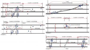
Appendix A
These are the diagrams being used by one major gas pipeline company to determine class location and pipe stress level. House counts should be redone every few years as the population increases.
Appendix B
Attached is a curve that shows the required horsepower to compress a million cubic feet of gas at different compression ratios.
The Author
George W. White was Vice President and Chief Engineer for Tenneco Gas Pipeline Company for 20 years during the boom days of the gas pipeline industry. He designed several large gas pipeline systems which are now in service. He was chairman of the Line Pipe Users Committee of the American Petroleum Institute (API). He was also secretary of the American Society of Mechanical Engineers (ASME) B31.8 Committee for Gas Piping Standards. He also served for several years on the Technical Pipeline Safety Standards Committee of the Office of Pipeline Safety of the federal Department of Transportation and was instrumental in the writing of 49CFR Parts 191, 192, 193 and 195. He graduated from Rice University in 1950 with a Bachelor of Science Degree in Mechanical Engineering and was a registered professional engineer in 16 states. He retired in 1984 and resides at 21303 Palomino Cove, Lago Vista, TX 78645. He will be 90 in November and can be reached at 512 267-0073.

Comments