
September 2011, Vol. 238 No. 9
Features
Pipeline Route And Depth-Of-Cover Survey Considerations
Geophysical and geotechnical survey techniques used for shallow water pipeline route investigations can also be used to determine the pipeline depth of burial in shallow water regimes. Multidiscipline surveys enable: 1) mitigation of risks from natural or man-made seafloor hazards; 2) regulatory compliance (archaeological, integrity management, shallow hazards); and 3) establishment of design criteria for pipeline, cable, template, etc.
By operating several data acquisition systems simultaneously, a wide range of survey objectives can be accommodated quickly, minimizing survey costs to client companies.
Multidiscipline survey techniques will provide data not only for depth of cover but can identify the conditions of the pipeline trench, backfill material, surrounding surficial soils, seafloor scour along the pipeline, debris and proximity to other pipelines. Accurate position information is recorded along with the systems data.
By simultaneously operating several systems, a quick determination of conditions that may have an effect on an existing or planned pipeline installation can be realized. A typical system suite includes: 1) positioning – DGPS, 2) subbottom profiler – Chirp, 3) echo sounder – dual frequency, 4) sidescan sonar – dual frequency, and 5) magnetometer – low noise.
Depth Of Cover
Let us consider pipeline depth-of-cover survey techniques – shallow water operations. Four primary approaches are typically used to measure depth of soil cover over an existing pipeline: a) physical probing from the water surface or by diver, b) gradiometer array, c) pulse induction system, and d) chirp subbottom profiler.
The following discussion details the subbottom profiler utilization as it is considered the most effective and least costly survey method of the three. In addition, when other complementary survey equipment is used, additional important data are available to the operator
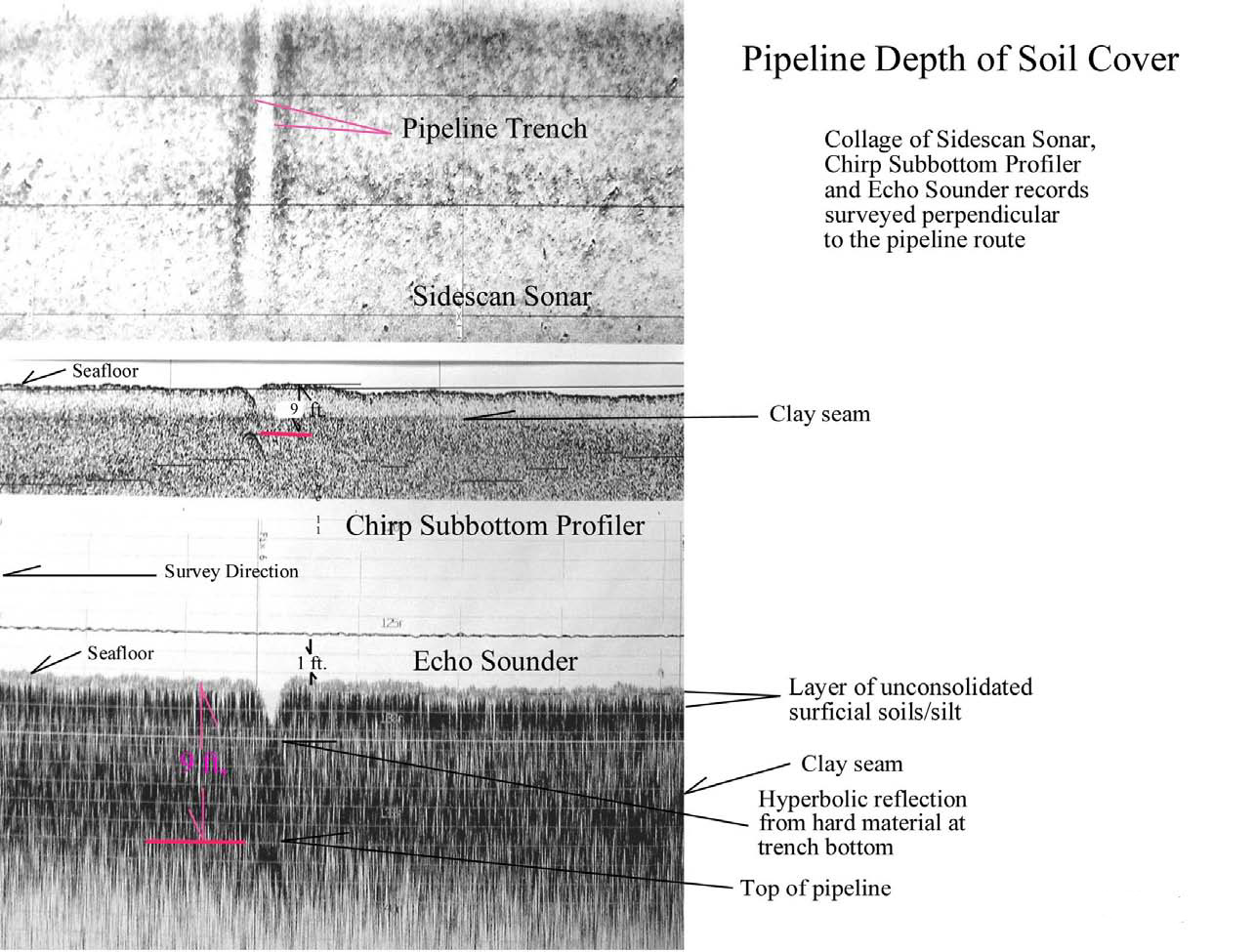
Figure 1 illustrates typical data provided by a sidescan sonar, subbottom profiler and echo sounder when operated over a pipeline. Additionally, a magnetometer is used to assist in determining the exact location of the line.
Typically, a dual-frequency echo sounder (30 kHz – 200 kHz range) and a subbottom profiler are used to determine depth of cover. The higher frequency system inherently is the most accurate due to a narrow beam width, shorter pulse length and wavelength provided. Specifications for the A typical hydrographic profiler operating at 200 kHz provides accuracy as .01 m 1% water depth. In the case of depth of cover, we are concerned with the window between the seafloor surface and the top of the pipe which will normally be less than 10 feet. In this case, the accuracy would be better than .01 m (.4 inch) + 1% of 10 feet (1.2 inch) or 1.6 inch maximum error.
The sediment within the depth of interest is water-saturated and acoustic velocities are considered identical to that of the water column.
With reference to Figure 1, we can observe the depth of the pipeline from the seafloor to be nine feet. However, due to scour or lack of backfill we also can see the pipeline is six feet from the bottom of the trench. It would be difficult, at best, for a diver to determine where the actual seafloor surface is in respect to the trench bottom and the pipeline.
The lower frequency echo sounder (24 kHz –30 kHz) is able to penetrate a soft bottom to several feet, in the case in Figure 1, the partially suspended surficial sediment (flocculent, fluid mud or fluff), a second somewhat more settled material at one-foot depth (natural sea floor), and a clay seam at nine feet, are identified.
The subbottom profiler record clearly shows the clay seam but, due to the lower operating frequency, cannot resolve the softer material near the surface. The footprint of the transmitted pulse is much wider than that of the echo sounder, allowing it to map the pipeline from a greater horizontal distance. The acoustic pulse from the profiler is less subject to attenuation and can function more effectively in noisy sea conditions.
The sidescan sonar transmits a narrow beam in the azimuth and can be very effective in determining if the seafloor has been disturbed along the pipeline. The example shows that the trench has not been affected by significant scour and that the pipe remains buried out to the limits of the record (approximately 50-meter swath).

Figure 2: Depth-of-cover record examples from SBES (35 kHz) and CHIRP subbottom profiler systems.
Multiple Acoustic Systems
When a single beam echo sounder (SBES) is used along with a “Chirp” subbottom profiler, enhanced correlating data can be obtained. The SBES resolution is greater due to the higher frequency and pulse repetition rate. The “Chirp” can penetrate to greater depths and provide data in soils that can limit penetration of the SBES. Pipelines with diameters of four inches can be easily mapped under normal conditions.
In areas where soil conditions between the pipeline and seafloor are disturbed (i.e., gas charged sediments, backfill, sea grass, shell, fine sand), the pipeline signature can be obscured. By using special filters and trace gain adjustments, pipeline detection can be enhanced. When the acoustic signature and frequency response of the seafloor sediments are analyzed, the minute amplitude variance from a pipeline can be detected and mapped more easily.
The systems can be operated in very shallow water depths using special tow and transducer mounting configurations. The limit of shallow water operation is limited primarily by vessel draft. The Chirp subbottom profiler – due to the correlation processor – can operate very effectively in water depths of less than 10 feet (Figure 3). In fact, several surveys in water depths of less than three feet have been conducted by the author. Typical discrete frequency (i.e. 3.5 kHz/6 kHz) profilers are limited as transducer ring extends to 3 ms from the time break, masking data for the first 10 feet beneath the transducer.
The primary limiting operational factor is excessive noise on the geophysical records caused by rough sea conditions. Depending on sea conditions, the sidescan sonar tow fish can be operated from the bow or stern.
Probing as a method of determining depth of cover is difficult and inherently inaccurate due to vessel heave, angle of measurement and the inability to define the “natural” seafloor surface.
Diver probing improves accuracy but can be slow and costly.
When taken from the survey vessel, probes can be a value-added asset to assist confirmation of targets identified by acoustic systems where results may be mitigated by gas-charged surficial sediments, sand, shell or sea-grass.
Portable Gradiometer
In areas where a pipeline crossing point is difficult to determine using only the acoustic systems, this instrument – when towed or attached to a pole – can prove to be a valuable tool. An audible tone is generated when the sensor passes over a pipeline and has a range of several meters beneath the sea floor, depending on soil conditions. It can greatly reduce probing time, in many cases.
Magnetometer
The marine magnetometer produces a strong signature when a pipeline is crossed and is often the most effective system in initially locating a buried pipeline. The acoustic systems can then be used to record more detail.
Simultaneous operation of a magnetometer, sidescan sonar, subbottom profiler and single beam echo sounder (SBES), can provide position data, depth of cover, seafloor sediment regime, and orientation of buried pipelines, cables, wrecks and debris.
Pulse Induction Technique Alternative
The system when mounted on a tow sled can allow for detection of pipeline and burial depth when acoustic signatures cannot be obtained with a subbottom profiler. Though lacking the depth-of-cover accuracy of an acoustic system, the alternative can be effective for river crossings, bayous and areas of disturbed sediment. Disadvantages include slow survey speed and it is somewhat cumbersome to handle.

Soils Stability
A geophysical profile of the soil conditions along the pipeline asset can be recorded and entered in a GIS data base and matched with data collected during subsequent survey efforts. This can be done during a routine depth-of-cover investigation. This is particularly useful in marsh areas where localized currents may affect security of portions of a pipeline.
Sidescan sonar records along with backscatter data recorded by the swath systems are used to assist in determining the character of the seafloor sediments for design and installation planning as well as detecting seafloor scour.
Grab Samples
A Mini-Ponar is a portable, lightweight grab sampler. The samples can be used to help identify surficial soils characteristics and can be a valuable tool to assist in field interpretation of geophysical data. The samples can be bagged for later laboratory testing.
Geotechnical Correlations
Soils samples acquired at locations chosen after preliminary interpretation of geophysical survey data can prove to be a valuable asset in the determination of soils regimes in a survey area. Acoustic reflective horizons from a subbottom profiler or dual frequency echo sounder can often be correlated with soils samples to allow identification and mapping of sedimentary and stratigraphic sequences. Backscatter data from the multibeam sonar and sidescan sonar data can help determine the lateral extent of the surficial sediments identified.
Reflectivity of seafloor sediment materials can be ascertained by recording acoustic images and sediment classification determined following data processing and correlation with ground truth data. 4D surveys (XYZ and Time) may help monitor scouring or migration of surficial soils due to storm induced currents along pipeline assets. GIS database can be developed for specific survey data. The data can be extracted from sidescan sonar, multibeam sonar or single beam sonar.
This technique may be applied during pipeline depth-of-cover surveys. This could be very useful in monitoring erosion, scour, subsidence, seafloor current regimes and changes in thalwegs in navigation corridors.
In Review
Advantages of a multidiscipline pipeline route survey approach using a suite of instruments are several:
• Depth of cover can be determined quickly as the survey boat acquires data at approximately 3-4 knots.
• Measures thickness of flocculent and accurate determination of the “natural seafloor” as required under the guidelines of the D.O.T. for measuring pipeline depth of cover.
• Accuracy of the high frequency echo sounder exceeds 1.6 inches in the material covering the pipeline.
• The sidescan sonar can provide information along the pipeline trench showing breaches or seafloor scour.
• Seafloor characteristics will be represented by acoustic reflectivity of the sidescan sonar, subbottom profiler, and echo sounder data.
• Accurate 3D position of the pipeline crossing location using the magnetometer, echo sounders, subbottom profiler, sidescan sonar and DGPS positioning.
• Using a gradiometer/pulse induction array, data can be obtained in problem areas, including sand, gravel, sea grass, gaseous sediments.
• Economical since all systems are used simultaneously with one mobilization.
• Data recorded digitally for conversion to client-specified GIS format. A program can be designed and integrated into an “Integrity Management Programs” required by the D.O.T. Office of Pipeline Safety
(49 CFR 192&195).
In conclusion, various approaches have been successfully used to determine pipeline depth-of-cover in the shallow water marine environment. All techniques have inherent advantages and disadvantages. Not all systems work in a particular environment. At times, no system will provide satisfactory results, particularly in river and estuarine environments or where there may be excesses of biogenic gas-charged sediment, rock berm over a pipeline, sand, sea grass or areas with multiple pipelines in the area.
A survey approach should be developed to satisfy the project objective, taking into consideration the environment of the survey location. Systems utilization and survey methodology can be designed to produce the most cost-effective and technically appropriate results.
Survey contractors prefer to use company-owned equipment for survey operations to minimize costs. This can be a real advantage; however, if technical satisfaction of survey objectives can be best served by using systems deemed more appropriate, consideration should be given to their application.
Author
Richard M. Seeger is president and CEO of SeaScape Technical Resources, Inc., Houston. His experience spans four decades in operations and business development in the areas of marine geophysical, geotechnical and oceanographic surveys in more than 40 countries. His previous experience also includes serving as sales and operations manager – marine surveys for D’Appolonia Consulting Engineers, Inc.; operations and sales manager, Decca Survey (Latin America), Inc.; sales engineer, Edo Western Corp.; and operations manager, Teledyne Exploration Co. He can be reached at Richard@SeascapeQC.com.

Comments