
March 2011, Vol. 238 No. 3
Features
Observations From 56 Years Of Pipeline Corrosion Damage Excavations
The author began working as a cathodic protection (CP) practitioner in August 1952 and, in 1954, conducted tests while observing his first excavation of a leak on a coated steel pipeline under CP near Moran, KS.
This article presents information learned from the 1954 corrosion leak site along with four later corrosion damage sites investigated during excavation by the author. It begins with the most recent investigation.
Author’s Note: In this article many of the pipe-to-soil (P/S) potential measurements will be given only to the decimal place, such as -1.10V, -1.09V, -0.94V, etc. The advent of the high impedance input digital voltmeters has led to the improved contemporary practice of recording P/S potential measurements to the third decimal place. All P/S potentials discussed in this article were measured to a copper sulfate electrode (CSE) with a potentiometer voltmeter or a digital voltmeter with an input impedance of 10 mega ohms or greater.
Investigation Number 1
March 31, 2009 near Mont Belvieu, TX.
10-year-old, 12-inch (30.5 cm) diameter pipeline.
Pipe Coating: Extruded Polyethylene.
Field Joint Coating: Heat Shrink Sleeve.
Pipe Cover: 70 inches (1.78 m) in 400-1,000 ohm-cm soil.
CP System: Rectifier–Deep Anode Groundbed System.
Pipeline ROW: Open grazing land.
P/S Potential on: -1.352V.
P/S Potential off: -1.095V.
P/S Potential on CSE at pipe: 1.341V.
P/S Potential off CSE at pipe: 1.087V.
An inline inspection (ILI) tool was run through the pipeline to determine if areas of pipe wall metal loss existed along the line. An area of metal loss on the external surface of the pipe was located by the tool. This location was excavated for visual inspection. As shown in Figure 1, a large calcareous mass has been deposited by the pipeline’s cathodic protection system over a defect in the heat-shrink sleeve used to coat a field joint girth weld.
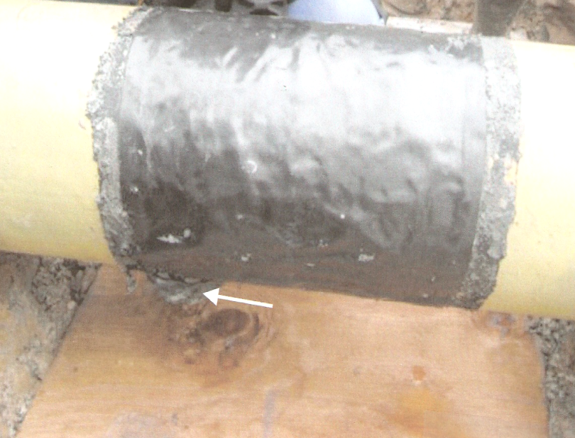
Figure 2 shows an enlarged view of the calcareous deposit above the plywood board that was placed under the pipe to prevent the inspector’s boots from miring in the mud.
Figure 2

Figure 3 shows the calcareous deposit from a view beneath the pipe. It appears that the pipe was slid on the soil to position it in place after the heat shrink sleeve was installed.
Figure 3

The heat-shrink sleeve and calcareous deposit were removed and, as shown in Figure 4, a string of corrosion product buildup was found along the line where the heat shrink sleeve was disbonded from the pipe.
Figure 4

The rough appearing surface to the left of the corrosion product buildup is the heat shrink sleeve adhesive that remained on the pipe after the sleeve was removed. Note that the pipe was not corroded beneath the calcareous deposit, but was corroded beneath the disbonded heat-shrink sleeve.
Figure 5 shows the pipe after further cleaning which shows pitting of the pipe to 100 mils (2.54 mm) deep beneath the corrosion product buildup.
Figure 5

Investigation Number 2
Feb. 2, 2009 near El Dorado, AR.
29-year-old 10-inch (25.4 cm) diameter pipeline.
Pipe Coating: Coal Tar (tar, fiberglass and felt) TGF-3.
Field Joint Coating: Tape.
Pipe Cover: 40 inches (1.02 m) in 3,600 ohm-cm soil.
CP System: Zinc anode grounding cells and rectifiers.
Pipeline ROW: Paralleling other pipelines and a high voltage power line in forest land.
P/S Potential: -1.200V,CSE on surface of soil.
P/S Potential: -1.177V,CSE at pipe.
The zinc anode grounding cells were installed on the pipeline during construction to provide grounding to protect the workers and the pipe from induced AC voltage and ground fault voltages from the paralleling power line. Bonds were installed shortly after construction to provide rectifier current for the pipeline.
An inline inspection tool was run through the pipeline to determine if areas of pipe wall metal loss existed along the line. An area of metal loss on the external surface of the pipe was located by the tool with a notation of, “metal in close proximity.” This location was excavated for visual inspection. As shown in Figure 6, a piece of ½-inch (12.7-mm) steel banding material was in contact with the pipe.
Figure 6

Note the calcareous deposit on the steel band and the large calcareous deposit over the holiday in the coating at the steel band’s contact with the pipe. The calcareous deposit was removed and, as shown in Figure 7, some of the pipe coating was removed to obtain a better view of the pit in the pipe.
Figure 7

It appears the corrosion was no longer active in the pit and it had stopped when the pit became deep enough to break the contact between the steel band and the pipe.
Investigation Number 3
November 1992 near Webster, TX.
34-year-old 4-inch (10.2 cm) diameter pipeline.
Pipe Coating: Coal Tar TGF-3.
Field Joint Coating: Hot Coal Tar.
Pipe Cover: 20 inches (50.8 cm) in 400-500 ohm-cm soil.
CP System: Magnesium anodes.
Pipeline ROW: In high-voltage power line ROW in open grazing land.
P/S Potential: -1.11V,CSE on surface of soil.
P/S Potential: -1.09V,CSE at pipe.
The pipeline was installed in a high voltage power line ROW in 1958. Magnesium anodes were installed alongside it in 1959 to provide CP and grounding for mitigation of induced AC voltages and ground faulting from the multiple paralleling power lines in the ROW. From the early 1900s to shortly after World War II, the power line ROW was also the ROW for an electrified trolley car railroad.
The magnesium anode system was diligently monitored and depleted anodes were diligently replaced. Also, the number of anodes required for satisfactory grounding was more than needed for CP so some of them could be depleted without compromising the CP of the pipeline. A leak occurred on it in November 1992 near Webster, TX.
Water was pumped into the pipeline to displace the hazardous product in it. Before the arrival of machinery to excavate the pipe, it was found that the pipe was leaking water and, in the process of measuring the P/S potential with the CSE on the surface of the soil, at the top of the pipeline and at the bottom of the pipeline, it was found that the pipeline was 20 inches (50.8 cm) deep in soil softened by the water. Because of this condition, the decision was made to excavate the leak using hand tools.
It was soon determined that the water was leaking through a hole in the bottom of the pipe. One worker placed his hand under the pipe and informed that a wire was connected to the pipe where it was leaking the water. He was trying to find out where the wire went when the end of a 3/8-inch (9.5-mm) diameter wire rope sprang from under the pipe to about level with the top of the pipe. The wire turned out to be the junk steel cable (wire rope).
The operators of the pipeline replaced the necessary section of the pipeline and furnished the author with a 14-inch (35.6-cm) long piece of the pipe with the leak hole in the center of it. It was obvious that the junk wire rope was running parallel with the pipe ditch and protruded up from the bottom of the ditch about 6 inches (15.2 cm). The cable had penetrated the coating to contact the pipe and as the pipe metal corroded the cable under tension would move upward to fill the corroding pit in the pipe. This continued until the pipe wall was penetrated.
Except where the junk steel cable had penetrated it, the coating on the pipe was in excellent condition and firmly bonded to the pipe.
Investigation Number 4
June 1974 near Paradise, TX.
Six-year-old, 4-inch (10.2 cm) diameter pipeline.
Pipe Coating: Tape.
Field Joint Coating: Tape.
Pipe Cover: 42 inches (1.07 m) in 2,500 ohm-cm soil.
CP System: Magnesium anodes.
Pipeline ROW: Open grazing land.
P/S Potential: -0.92V,CSE on surface of soil.
P/S Potential: -0.90V,CSE at pipe.
The pipeline was installed in 1968. Magnesium anodes were installed on it at midpoints between test stations during its construction. To investigate the 1974 leak, water was pumped into the line to displace the hazardous product in it.
Upon arrival at the leak site investigators found the hazardous product that had leaked from the pipeline had frozen the soil around it and, although water was leaking from the pipe, there were thawing chunks of ice in the soil and water. As the pipeline was being excavated, it was determined that the water was leaking through a hole in the bottom of the pipe. A worker, using a putty knife to remove the material from under the pipe where the water was leaking, was asked what the brown material he was scraping from beneath the pipe was. He replied that it appeared to be “old rotten wood.” Further investigation revealed that, indeed, it was old rotten wood. He said, “there is a skid, 4 inches (10.2 cm) x 4 inches (10.2 cm), made of hardwood timber, right where the leak is.”
Investigation Number 5
Spring 1954, near Moran, KS.
Five-year-old, 12-inch (30.5 cm) diameter pipeline.
Pipe Coating: Asphalt.
Field Joint Coating: Hot Asphalt.
Pipe Cover: 32 inches (81.3 cm) in 1,800 ohm-cm soil.
CP System: Rectifier-conventional groundbed system.
Pipeline ROW: Wheat field.
P/S Potential: -1.11V,CSE.
The pipeline was installed in 1949 and a rectifier-conventional groundbed system was installed on it shortly after it was constructed.
The 1954 leak occurred at a dirt road fence where a test lead was on the pipeline. The excavation crew removed the fence to make room for excavating the pipe.
As the pipeline was being excavated, it was found that the leak was on the top of the pipe and that was the only place with damage to the coating. Workers mentioned during the excavation of the pipe that a hole in the soil seemed to be directly above the pipe. One worker stated that the leak was, “right where the anchor post for the gate was in the fence.” Inspection of the bottom of the anchor post revealed that it had some of the missing asphalt coating from the pipe on it.
The landowner had been paid to restore his fence when the construction of the pipeline was completed in 1949 and, in that area of Kansas, bois d’arc wood fence posts have been known to last as long as 75 years. So the landowner used bois d’arc wood posts driven in place with a tractor to build the fence and the gate post ended up being driven down on top of the pipeline. The gate post had prevented CP of the pipe under it from 1949-1954.
Conclusions
1. When a buried steel pipeline is in contact with decaying wood such as a wood skid that is commonly used during pipeline construction, CP cannot be relied on to control corrosion of the pipe in contact with the wood. CP may or may not control this type of corrosion, depending on the circumstances.
2. When a buried steel pipeline is in contact with a metal object, CP cannot be relied on to control corrosion of the steel pipeline at the point of contact.
3. When the author began work as a CP practitioner in 1952, the rule was, “don’t throw wood skids, welding rods, Vienna sausage cans, pork and bean cans, tuna cans, etc in the pipe ditch because it corrodes the pipe even with CP on the pipe.” So conclusions 1 and 2 are not divulging any new information.
4. The proper excavation procedure for investigating corrosion damage on a buried pipeline under CP is as follows:
A. Excavate with a backhoe until a shovel can be used. B. Excavate with the shovel until a spoon or putty knife can be used. C. Excavate with the spoon or putty knife until a tooth brush can be used. D. Brush to complete the excavation.
Acknowledgement
The article is based on paper Number 10033, “Field Observations From 56 Years of Investigating Corrosion,” presented at NACE International CORROSION/2010, San Antonio, TX.
Author
L.A. (Roy) Bash has more than a half century of experience as a corrosion control practitioner and consultant. He has been with Global Cathodic Protection, Inc., Houston, since 1992. He can be reached at 713-784-9588, ext. 10, e-mail care of angie@globalcorrosion.com, www.globalcorrosion.com.

Comments