
March 2011, Vol. 238 No. 3
Features
Exploring Drag-Reducing Grooved Internal Coating For Gas Pipelines
In the process of natural gas transmission, almost all power of the compressor stations is used to overcome the friction consumption between the flowing gas and pipeline wall. Therefore, large amounts of resources are spent on compressor station maintenance every year.
To increase transmission capacity and to save energy, internal coating technology has been widely applied in gas pipelines and a remarkable economic benefit has been achieved so far. However, with the roughness reduced on the inner wall, the small convex parts are all completely submerged in the viscous sublayer and the gas pipeline becomes “hydraulic smooth pipe.” That means even though the coating surface is smoothed further, the wall friction is difficult to further reduce. Therefore, in order to further increase the transportation capacity on the basis of internal coating, new methods and technologies should be researched and investigated. Perhaps the biomimetic drag-reducing technology is a good attempt.
Internal coating technology is the milestone in the history of natural gas pipelining, and its advantages are as follows: 1) improving the flowing properties, 2) anticorrosion provided before construction, and 3) helpful to detect the faults on the inner wall of pipeline [1]. Through several decades of effort, the internal coating technology has been vastly improved. Canada, Italy, France, the Former Soviet Union and the Netherlands all have adopted drag reduction internal coating technology, and the transmission rate was improved by, respectively, 3.8%, 6.2%, 10%, 12% and 30% [2]. China’s scientific researcher Linzhu and others carried out field tests in Dagang City. The results showed that the throughput of a natural gas pipeline with the AW-01 drag reduction internal coating was improved by 20.9% compared to the untreated pipeline [2]. At present, internal coating technology has been widely applied in China’s West-East Gas Pipeline Project and others under construction, which has brought enormous economic benefit.
Biomimetic Drag-Reducing Techniques
In 1970s, Michael J Walsh at NASA’s Langley Research Center found that ribbed surfaces can effectively reduce friction [4], which completely broke through the traditional way of thinking and opened up new roads of the drag-reducing technology.
Decades of abundant research has indicated that the biomimetic drag-reducing technology has very strong practicability, reliability and maneuverability. Present studies have entered the practical engineering stage and gratifying results have been obtained throughout the world. For example, David Taylor Naval Ship Research Institute pasted the grooved film (manufactured by 3M Corporation) onto a towed object and then drew the object in a pool, achieving a drag reduction of almost 2% [5]. Dresden Technical University pasted the riblets film into a pipeline, attaining a drag reduction effect of about 10% [6]. The research institutes of DLR Berlin performed the drag-reducing design of oil and gas pipelines lined with micro-grooved surfaces and found the transmission rate increasing on different levels; Han Xin, Zhang Deyuan and others adopted the bio-replicated forming method in fabricating the vivid shark skin surface, and the testing in a water tunnel showed that the friction of the vivid shark skin surface can be decreased by 8.25% [3]. Therefore, the inference is that the biomimetic drag-reducing technology has tremendous room for development.
Imprinting Micro-Grooves On Internal Coating Surface
The process of internal coating technology mainly involves the following key steps: drying, derusting, cleaning, spraying and curing [12], in which the latter two are more crucial. Based on the criteria used in China, the AW-01 epoxy resin is one of the selected coating materials [12]. What follows are looks at research aimed at this material.
According to the properties and characteristics of the thermosetting materials (epoxy resin), the advanced new technology discussed in this article is Pre Cured Micro-imprinting Technology (PCMT). The steps are as follows: 1) epoxy resin and curing agent are mixed completely by a mass ratio of 1:1, and then sprayed on the inner wall of the pipeline at a barometric pressure of 0.8 Mpa, the thickness of liquid coating is about 0.2 mm; 2) they are placed into drying room at 45 degrees C and, after 80 minutes, the mold is stacked on the pre-cured coating; 3) until the epoxy resin is completely cured, and then the temperature is slowly lowered to about 25 degrees C and the gas pipeline with the biomimetic drag-reducing coating can then be received by demolding.
In the course of manufacturing the grooved inner wall, for eliminating the errors of welding seam, roundness, straightness of pipeline and making the coating and mold contact each other completely, the elastic mold should be produced first. The steps are as following: 1) highly accurate cutting of the flexible grooved film [7]; 2) bonding the film on the inner surface of the cylindrical mold; 3) casting the silicon rubber and curing; 4) gaining the elastic mold by demolding. To ensure pressure exerted toward the inner wall, the diameter of the elastic mold should be more than that of the gas pipeline by about 2% to 5%, and, in the step of stacking the mold, it should be placed into the pipeline in a stretching station to temporarily reduce the diameter.
Figure 1 shows all steps of pre cured micro-imprinting technology on a gas pipeline. The micro-grooved surface coating on gas pipeline is shown in Figure 2.

Figure 1: Illustrations of the pre cured micro-imprinting technology on gas pipeline.

Figure 2: Micro-grooved surface internal coating on a gas pipeline.
Numerical Simulation Of Drag Reduction Effect
It is necessary to verify the drag reduction effect achieved on a biomimetic energy-saved gas pipeline, but the actual experiment is very complicated and difficult to be carried out at once. Therefore, the direct numerical simulation is a very good selection. The relevant field operation data of the pipeline from Jingbian to Yulin in Shannxin-Beijing trunk line (in January 2000) is as shown in Table 1 [14].
![]()
Table 1: Field operation data of gas pipeline.
Based on the parameters and relevant literatures, the thickness of sublayer on the gas pipeline is 33.1 um. AW-01 epoxy resin coating has dropped the average absolute roughness of the inner wall from 45 um to 5.5 um [12], so the gas pipeline has become “hydraulic smooth pipe.” In order to improve the drag-reducing effect further, the triangle groove is designed as s=135 um, h=100 um (s-width of the groove, h- height of the groove), where the tips of grooves stick out of the viscous sublayer, and the good drag reduction effect can also be received.
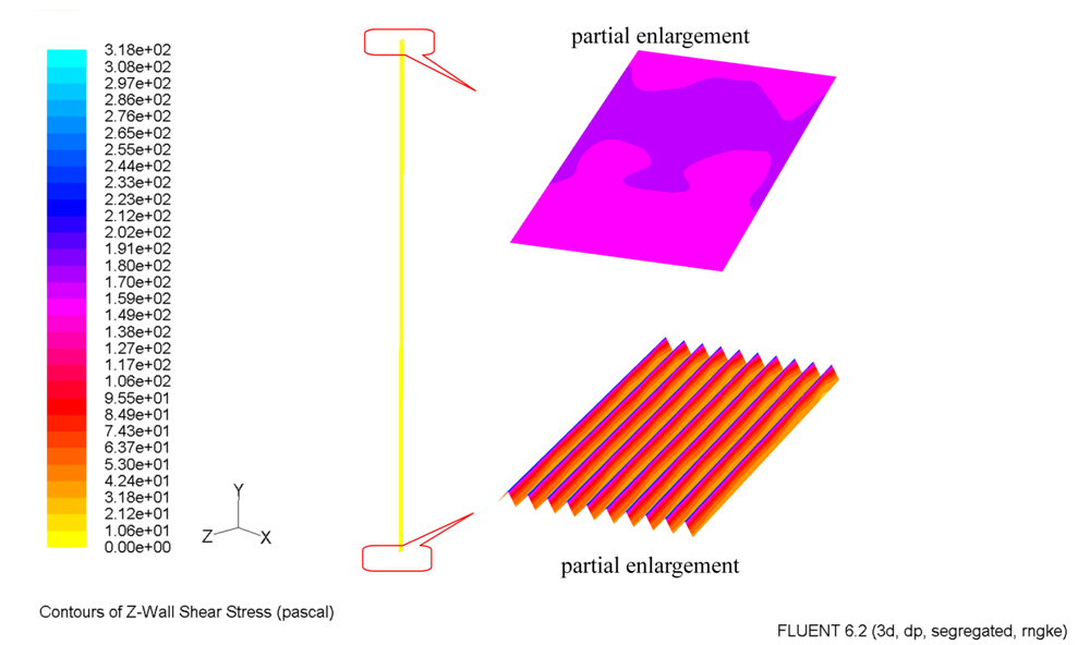
Direct numerical simulation is performed as discussed here. Figure 3 shows the contours of sheer stress on smooth and grooved surface, when the average velocity of gas in the pipeline is 4.03 m/s. For the grooved surface, the sheer stress on the tips and the valleys is about 286.44 pa~302.35 pa and 31.83 pa~47.74 pa respectively, and for the smooth surface, the sheer stress is unanimously about 159.13 pa~175.04 pa, and the integral of sheer stress on the smooth surface and groove surface is 0.001064 N and 0.0009968 N, so the drag-reducing efficiency of grooved surface is 6.32%. Therefore, the biomimetic energy-saved pipeline exhibits the drag reduction effect.
Economic Analysis
The relevant parameters in the West-East Gas Pipeline Project are shown in Table 2. Take, for an example, the economic analysis and calculation are analyzed and discussed.
![]()
Table 2: Designed parameters of West-East Gas Pipeline Project.
If the drag-reducing efficiency of the new-type gas pipeline is set as 6%, the number of pumping stations can be reduced to 17, which can lower the total cost about 370 millions yuan. The total saved gas consumption is about 32 millions m3. If the market price is calculated as 2.5 yuan/m3, the savings in natural gas cost is about 80 million yuan/year.
Due to the addition of new working procedures to the manufacturing of the micro-groove coating, the manufacturing costs will increase by about 10 yuan/m2, so the total additional cost is calculated as follows:
10yuan/m2×3.14×1.016m×3900×1000m=1.24×108yuan
Therefore, if the gas pipeline with micro-grooved coating can be installed, the total cost of investment will be reduced by about 246 million yuan and the cost saving is about 80 million yuan every year.
Acknowledgements
This work is supported by the National Natural Science Foundation of China (Grant No. 50775006), 863 Plan Key Project (Grant No. 2009AA043802). In addition, the authors would like to thank Jiao Ruyi and Zhang Baoqiang in Pipeline Research Institute of CNPC, who supplied the relevant data in this paper.
Authors
Zhang Deyuan (zhangdy@buaa.edu.cn) is a processor of Research Center for Bionics and Micro/Nano/Bio Manufacturing Technology, Beihang University, Beijing. He holds a Ph.D. (1996) from Beihang University. His major areas of research include bio-machining and biomimetic drag-reducing technology.
Luo Yuehao (luoyuehao1985@163.com) is a Ph.D. candidate in the School of Mechanical Engineering and Automation, Beihang University, Beijing. He holds a master of science (2008) from Jilin University, China.
References
[1] Hu Shixin, Qu Shenyang, Lin Zhu: Engineering Sciences, Vol. 2 (2004), p.50-59
[2] Lin Zhu, Zhang Liping, et al: Welding Pipe and Tube (in Chinese), Vol. 25 (2002), p.1-4
[3] Han Xin, Zhang Deyuan, Li Xiang & Li Yuanyue: Chinese Science Bulletin, Vol. 53 (2008), p. 1587-1592
[4] Michael J. Walsh: AIAA, Vol. 21 (1983), p.485-486
[5] A. Dinkelacker, K. Koeltzsch, R. Grundmann: Experimental Fluids, Vol. 33 (2002), p.346
[6]W. L. Sellers M. J. Walsh, G. B. McGinley: Journal of Aircraft, Vol. (1989), p. 570
[7] Li Xiang, Cai Jun, Zhang Deyuan: Advanced Materials Research, Vol. 97-101(2010), pp. 2533-2537
[8] D. W. BECHERT, M. BRUSE, W. HAGE, et al: J. Fluid Mech, Vol. 338 (1997), pp.59-87
[9]Liu Zhihua, Dong Wencai, Xiong Ying, Xia Fei: Journal of Ship Mechanics, Vol. 11 (2007), pp. 820-830
[10] D. W. BECHERT, M. BARTENWERFER: J. Fluid Mech, Vol. 206 (1989), pp. 105-129
[11] Wang Songling: Fluid Mechanics (Beijing, China Electric Power Press, 2007, in Chinese)
[12] Hu Shixin, Chen Xiangxin: Drag Reduction Internal Coating Technology on Gas Pipeline (Beijing, China Chemical Industrial Press, 2003, in Chinese)
[13] Huey J. Chen, Gene E. Kouba, et al: Oil & Gas Journal, June 5 (2000), pp. 54-58
[14] YANG Xiaohong, ZHU Weiling: Petro-Chemical Equipment (in Chinese), Vol. 34 (2005), pp. 25-28

Comments