
June 2011 Vol. 238 No. 6
Features
Dry Gas Seals For High-Pressure Gas Injection Compressors
The escalating worldwide demand for oil and the continuously rising prices are driving oil companies to explore new oil field resources. However, exploration also incurs increasing expense in terms of technology. Many of these projects have a common need in that natural gas, which is associated with crude oil, has to be re-injected into the reservoirs.
The required injection pressure can reach values up to 800 bar (11,600 psi). Sophisticated ultra-high-pressure centrifugal compressors cover this application. The seal solution for the main shaft seal of the machines is based on the well-proven Dry Gas Seal (DGS) technology.
This article describes Dry Gas Seal solutions in centrifugal compressors used in extreme high-pressure service for gas injection. It provides a summary of the R&D and qualification programs for the seals and explains design features and operating limits.
Leading oil companies are continuously increasing their investments to satisfy global hunger for energy. A typical example is the exploration of the Tengiz and Kashagan oil fields in the Caspian region. The Kashagan field, one of the largest reservoirs discovered in the past 30 years, has an estimated recovery of 13 billion barrels of oil. One major technological challenge is compressing the associated, highly corrosive sour gas to ultra-high-pressure for re-injection. A compressor train, consisting of three centrifugal compressors driven by a 30-MW gas turbine, undertakes the high-pressure service.
Based on the expectation of a growing demand for ultra-high-pressure shaft seals, EagleBurgmann, in 1996, started an R&D project to develop dry gas seal technology for extreme pressures. In 2000, the European Union sponsored a joint project, the Method Project. Among the project partners were the University of Florence, GE Oil & Gas and EagleBurgmann. The Method Project’s objective was to evaluate the feasibility of a DGS operated at a pressure of 560 bar (8,120 psi). From this project were derived valuable insights into the special requirements for a DGS operated under extreme conditions.
In 2005, EagleBurgmann was invited by GE Oil & Gas to join a qualification program for a DGS to be operated at 425 bar (6,160 psi).
Operating Conditions
Gas-injection service at extreme high pressure is undertaken by a compressor train, consisting of three centrifugal compressors (LP, MP, HP), driven by a gas turbine. Table 1 shows the typical design conditions for the Dry Gas Seals.
Table 1: Typical design conditions for high-pressure dry gas seals.
Seal Design
The state-of-the-art sealing system for natural gas compressors is the Tandem Dry Gas Seal with intermediate labyrinth. The seal (Figure 1) consists of a series of two consecutive single seals. In normal operation, the pressure decreases via the seal face of the main seal (1) to a flare pressure, which is only slightly higher than atmospheric pressure. The secondary seal (2) operates under flare pressure, but can operate under full process pressure in the event of a failure. The main seal is supplied with filtered process gas (Connection A). An inert barrier gas (N2) is applied through Connection C. The pressure of the barrier gas is slightly higher than the pressure of the flare (Connection B), whereby a flow of gas through the labyrinth in the direction to the flare is obtained. The leakage of the main seal is guided to the flare, which prevents a leakage of process gas to the atmosphere.
To prevent the sealing element material from extruding, the extrusion gap should be designed as small as possible. The functional gap is the gap between the balancing sleeve and the support ring (Figure 2). However, a free movement must be ensured under all operating conditions. The functional gap’s design must be no more than a few hundredths of a millimeter. This very small gap value is a tough challenge to manufacture precisely because the variation of the gap height under the influence of temperature and pressure has to be minimized. To achieve this, extensive FE-calculations were carried out prior to design finalization.
Figure 2: Principle of design: dynamic secondary seal.
At ultra-high pressures, there are tremendous forces caused by the pneumatic load acting on the DGS not only in the radial direction, but also in the axial direction. To ensure maximum stability of the DGS at such high loads, the cross-sections of the metal sleeves in the seal cartridge have to be larger than those operating at lower pressures. In standard designs for low- and intermediate-pressure-range DGS, a sleeve design with an adapter sleeve is used, which is assembled above the shaft sleeve (Figure 3a). If only one sleeve is used for the ultra-high-pressure DGS, the relatively small cross-sections would be too weak to handle the high axial load. Therefore, in the ultra-high-pressure design the sleeves are split (Figure 3b) to ensure maximum stability of the DGS.

Figure 3a: Schematic picture of a low-pressure design with one shaft sleeve.

Figure 3b: Schematic picture of a high-pressure design with two sleeves.
The final seal design is shown in Figure 4. This seal is designed for a shaft diameter of 140 mm.

Figure 4: Cross-section of the ultra-high-pressure DGS.
Theoretical Evaluation
An extensive computational analysis was performed in the course of the development of the high-pressure compressor seal. This analysis focused on three different areas: 1) the detailed features of the seal face design with respect to the primary ring and mating ring (e.g. manufacturing taper, groove design, tuning step etc.); 2) the structural analysis of major seal components subject to the seal gas pressure; and 3) the detailed design of the two components’ support ring and tungsten carbide sleeve defining the extrusion gap.
Some detailed features of the rotating and stationary ring are essentially the outcome of computational analyses, in particular the groove design, the tuning step and the manufacturing taper. The basic analysis tool is a coupled fluid-structure solver specifically designed for the analysis of mechanical seals.
The general objective in any seal design is optimal seal performance and safe running throughout all operating conditions. However, seal design can become problematic when extreme operating conditions are present and a large number of design parameters have to be handled. In addition, there are rarely isolated effects, i.e., variation of a single-design parameter will normally affect all significant performance parameters. Moreover, the effects are often contradictory. For example, although increasing the initial taper will essentially improve the lift-off characteristics, at the same time, the radial gas film stiffness and seal performance at maximum speed will deteriorate.
Figures 5a and 5b show some essential seal parameters, in the p-n domain, for operation with methane as seal gas. Only a comprehensive view provides the necessary information to confirm or dismiss a design. This visualization of result data provides a comprehensive survey of the behavior of the most relevant seal parameters or the seal performance. Thus, weak points and insufficient safety margins are easily detected. It is clear that one single result parameter is not enough to assess a proposed design. Obviously, the start-up at maximum pressure is the most severe running condition since the operating gap reaches the lowest value. The test must prove that the design values are still sufficiently large to avoid circumferential rubbing marks caused by too small gap sizes.
Essentially, the groove design controls the characteristics of the seal. Unfortunately, one may not simply opt for a design having considerable safety margins with respect to minimum gap height at low speed and maximum pressure. Such a design would certainly lead to excessive leakage rates at high speeds and high-pressure levels. Any seal design, and this particularly applies to high-performance seals, must therefore remain a compromise that accounts for all required operating conditions as best as possible.
The high level of accuracy in prediction was demonstrated by comparing calculated and measured leakage values. The predicted leakage value for the main operating conditions compared very well with the measured leakage in the actual tests. The deviation was less than ±15%.

Figure 5a: Calculated seal performance: leakage for methane.

Figure 5b: Calculated seal performance: minimum gap for methane.
In order to prove their structural integrity, the core parts of the seal were subject to an extensive theoretical evaluation. The Finite-Element-Analysis was performed using ANSYS. Axis-symmetric modeling was applied.
Inboard seal (IB) and outboard seal (OB) were analyzed as individual configurations using linear and non-linear material models, respectively. The target was to evaluate stress distribution and deflection in several load cases such as “static condition,” “normal dynamic operation” and “upset operation with a broken seal face.” As an example, Figure 6 shows the von Mises stress distribution for “normal operation.” The stress level in all zones was found to be clearly below Rp0.2 (850 N/mm2 for Inconel® 718 in precipitation heated condition). A small zone of high stress level was found in the inner flange corner of the shaft sleeve. However, it does not compromise the mechanical stability of the shaft sleeve.
Figure 6: The von Mises stress distribution at P = 425 bar and n = 12,500 r/min.
Special attention was given to the behavior of the extrusion gap at the dynamic secondary seal (Figure 2). The extrusion gap is the radial distance between the outer diameter of the tungsten carbide sleeve, which corresponds to the hydraulic diameter, and the inner diameter of the support ring (Figure 7). On the one hand, this gap must be small enough to avoid extrusion of the PTFE element and, on the other hand, it must be large enough to avoid contact between both parts, the sleeve and the support ring.
Since the same material is applied for the sleeve and the support ring, the thermal expansion rate will be the same for both parts. The objective now is to find an optimal design that allows minimal variation of the gap size throughout all loading conditions. This design must account for two important facts: 1) there will be a relative axial movement between the sleeve and the support ring, which will change the loading on the sleeve and significantly affect the deflection; and, 2) tensile stress on the inside of the sleeve must not exceed a defined limit.
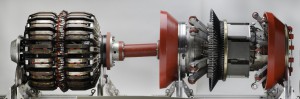
Figure 7: FE – model for analysis of the deformation behavior of the extrusion gap.
Test Program
The seal cartridges were tested in the EagleBurgmann test facilities, according to customer specifications, up to a maximum pressure of 425 bar. Different operating conditions were simulated in several test steps. After each test step, the seals were inspected.
As a follow-up to the EagleBurgmann shop test, a 16-day validation and endurance test was performed at the facilities of the compressor manufacturer. Two seals were tested in an ultra-high-pressure compressor. Table 2 shows the entire qualification program.
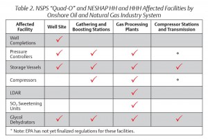
Table 2: Qualification program for high-pressure seals.
The EagleBurgmann shop test was performed on a high-speed test rig with a maximum pressure of 425 bar and a maximum speed of 12,373 r/min. Test gases were air and a helium/air mixture. A slow roll test was performed at a speed of 1,000 r/min. To simulate an axial displacement between the seal housing and the shaft, a hydraulic piston was integrated. An inductive sensor measured the axial displacement. To monitor the temperatures in the seal cartridge, thermocouple wires were applied in several positions. Typical test results for the Inboard seal test are shown in Figure 8.
 Figure 8: Seal performance of the inboard seal test at full speed and pressure.
An extensive validation test was performed at the compressor manufacturer’s facilities. The compressor was operated with pure methane. During the 16-day test period, including several stops and restarts of the compressor, the performance of the seal was consistently within the expected range and very stable.
Summary
The test program performed on Dry Gas Seals designed for ultra-high-pressure compressors showed that the challenge of sealing at this high-pressure level could be achieved with DGS technology. Based on this experience, it will be possible to manufacture seals for a design pressure of 450 bar. Nevertheless, EagleBurgmann is continuing the R&D program on high-pressure seals to increase the maximum pressure limit up to 550 bar and to ensure optimum reliability even in this pressure range.
Authors
Dr. Peter Droescher is manager, Engineering Compressor Seals. He received a mechanical engineering degree from the University of Applied Sciences, Munich. In his 20 years with EagleBurgmann, he has acquired extensive knowledge about mechanical sealing technology. Contact via Anita LaFond, Constructive Communication, Inc., 973-992-0715, alafond@constructivecommunication.com.
Dr. Michael Sattler is vice president, Global Application Engineering. He has 20 years of professional experience comprising all aspects of dry gas seals and seal control units for compressors including product management, marketing, application engineering, commissioning, and troubleshooting. He joined EagleBurgmann in 1989 after receiving his industrial engineering degree from the University of Applied Sciences in Munich.
Dr. Andreas Schruefer is senior expert R&D. He has a Ph.D. degree in the field of Dry Gas Seal technology. He has been employed at EagleBurgmann for 20 years. His expertise is in mechanical seal development, ranging from pump seals and agitator/mixer seals to compressor seals. During the last few years, Schruefer has been focusing on high-pressure dry gas seal technology and on the development of crystalline diamond coatings for mechanical seals.
Dr. Armin Laxander is senior engineer R&D. Dr. Laxander received his Ph.D. degree in aerospace engineering in 1996 from the University of Stuttgart. After holding several positions in the aerospace industry, he joined EagleBurgmann in 2002 working in numerical analysis for dry gas seals.
Bibliography
“Computational analysis methods for dry gas seals,” by A. Laxander, K. Lang, R. Johannes (2005), Workshop Advanced topics and technical solutions in dynamic sealing, Poitiers.
“Principles and Design of Mechanical Seals,” by A.O. Lebeck (1991), published by John Wiley & Sons, Inc., New York.
“2005 Financial & Operating Review,” ExxonMobil (2006), Irving, TX, USA.
“Dimensions of a seal – BURGMANN DGS for Compressors (2001),” Brochure by Burgmann Industries GmbH & Co. KG, Wolfratshausen.

Comments