
July 2011, Vol. 238 No. 7
Features
The Fundamentals Of Pipeline Gas Chromatographs
Gas chromatographs (GCs) are installed all over natural gas pipeline networks, providing an analysis of the flowing gas and calculating the physical properties used for the flow calculations and for custody transfer. However, a clear understanding of just how the GC works and the considerations that need to be made for the installation and operation of the GC are often lacking in the industry. This article discusses the major components of the GC and provides an understanding of the theory and practice of gas chromatography in the pipeline industry.
Natural gas in a pipeline is a mixture of hydrocarbons and diluents such as nitrogen and carbon dioxide. The composition of the mixture varies considerably and therefore the physical properties of the gas, such as the energy content (Btu or kilojoules) and density (lbs/cf or kg/m3), also vary. The job of the GC is to measure the concentration of each of the components so the physical properties can be calculated. The GC does this job in a three-step process: the first step is to take a fixed volume sample of the gas; next is to separate the mixture into the individual components; and finally the individual components are measured. The time taken to do these three steps depends on the type of GC and the degree of detail of the analysis, but typical C6+ GCs perform this cycle every three to four minutes.
Taking The Sample
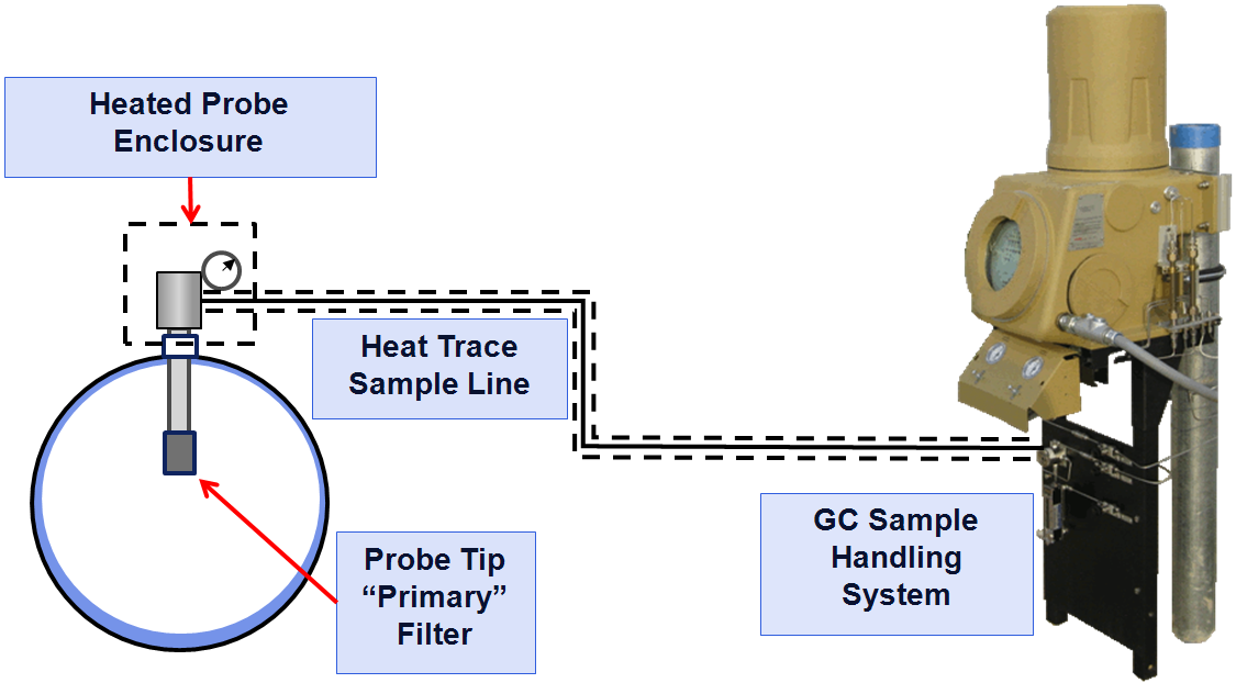
The maxim “garbage in – garbage out” applies to taking a sample for a GC analysis. The world’s best chromatograph will still give incorrect readings and cause errors in the custody- transfer calculations if the gas it is analyzing is not representative of the flowing gas in the pipe. To take a sample from the flowing gas stream, a sample probe will take a representative sample away from the liquid and solid contaminants usually found on the pipe wall. Any solid (down to at least two-micron) or liquid contaminants should be removed from the sample, and the pressure reduced to between 15-30 psig (100-200 kPaG).
When the pressure is reduced, and the sample is transported to the GC through the sample lines (typically 1/8-inch stainless steel tube), the temperature of the sample must not drop below the hydrocarbon dew point (HCDP) as this will result in the heavy components (also the high energy content components) dropping out into the liquid phase (forming condensate or “drip”) and the gas sample will no longer be the same as what is in the pipeline. To avoid dropping out any of the components from the sample, the API 14.1 standard recommends all the sample components should be heated to at least 30°F (16.6°C) above the expected hydrocarbon dew point (API 2006) using heated regulators and heat-traced sample lines. Figure 1 shows how these components fit together on the typical pipeline natural gas application.
When the sample reaches the GC, it will go through the local sample handling panel that provides the “last line of defense” particulate and liquid filtration and the stream selection valves. The sample fills a fixed volume sample loop that is injected into the chromatograph. To ensure the sample size is not affected by variations in the sample pressures of different streams, the sample loop is equalized to atmospheric pressure and the sample is injected into the columns.
Inside The Oven
The analytical components of the gas chromatograph (the columns, valves and detectors) are enclosed in a heated oven compartment. The performance and response of the chromatograph columns and the detectors are very susceptible to changes in temperature, so the oven is designed to insulate these components from the effects of ambient temperature changes and maintain a very stable temperature internally. A GC’s performance is directly correlated to the temperature stability of the columns and detector, so the temperature control is typically better than +/- 0.5°F (+/- 0.3°C).
The sample is injected into chromatographic columns that separate the components of the gas by some physical property. To inject the sample into the columns, the carrier gas pushes the components out of the sample loop and into the columns. The carrier gas is an ultra-high purity gas that won’t interact with the components in the sample and isn’t a component of interest in the measurement. Helium is commonly used in the natural gas application, but hydrogen is increasingly specified because of the rising prices of helium. For other applications, other gases such as nitrogen or argon may be used.
Chromatograph columns contain packing material that will interact with the components in the sample gas and selectively retard their flow depending on the physical property. The material is held in place by sintered metal filters at either end of the tube. The packing material consists of very small support material that has a very thin coating of liquid solvent. In some applications the separation is by molecular size (mole-sieve columns), but for most natural gas applications the molecules are separated according to the boiling point. In boiling point columns, the components with the lowest boiling point will travel faster than the components with the highest boiling point. If the column is long enough, the components will exit the column completely separated.
In a laboratory installation, a single long column may be used with the analysis taking up to 50 minutes. This is too long to wait in pipeline operations, so the separation of the components is broken up into portions that are handled separately by dedicated columns to accelerate the analysis times. For example, Figure 2 shows the oven configuration of the Danalyzer Model 500 C6+ that has three analysis valves, four columns and a single detector. Column one is the back-flush column that separates the hexanes and heavier components (C6+) from the normal-pentane and lighter components. Column two separates the propane to normal-pentane components, and column three separates the nitrogen, methane, carbon dioxide, and ethane. Column four is a buffer column that suppresses the flow disturbances caused by the valves switching, and separates any water or methanol from the C6+ peak. By breaking the analysis down like this, the analysis time is shortened to fewer than four minutes.

Figure 2: The internal flow paths of a typical C6+ gas chromatograph with three valves, four columns and a single detector pair.
The analytical valves switch the flow of the carrier gas and sample components at specified times through the analysis cycle. Analytical valves are highly specialized and have a very low dead volume, actuate very quickly, and can run for several years without maintenance while switching every four minutes, 24 hours a day. Over time, the valves will build up contamination that restricts the flow that, in turn, changes the time taken for the components to flow through the columns and on to the detector.
When this restriction to flow begins to cause the components to flow through the analyzer so slowly that the last components are being cut off at the end of the original cycle time, the valves should be overhauled. Overhauling the analysis valves is the most common form of maintenance on the gas chromatograph and requires the valves to be cleaned and the diaphragms to be replaced.
Once the components have been separated in the columns, they pass over to the detector to be measured. Several types of detectors are used in gas chromatography, including the flame ionization detector (FID), the flame photometric detector (FPD) and the thermal conductivity detector (TCD). The TCD is the most commonly used for the pipeline natural gas analysis because of its wide concentration detection range (ppm up to 100%) and the universal detection of all the components of interest. The TCD is a pair of thermistors that change in resistance in response to the change in the thermal conductivity of the gas passing over it. The thermistor bead has a constant current passing through it that causes it to increase in temperature. The amount of heat removed from the bead is dependent on the thermal conductivity of the gas passing over it.
Pure helium has a very high thermal conductivity and is always passing over the reference side of the detector. The components to be measured have a thermal conductivity lower than helium, and so – as they pass over the measure side of the detector – the amount of heat removed from the detector bead is reduced and the temperature of the measure detector bead increases. When the temperature increases, the resistance of the thermistor decreases. The difference between the reference thermistor and the measure thermistor is detected in a constant current Wheatstone bridge circuit that is amplified and processed by the gas chromatograph controller.
The Controller
The controller may be remote from the oven or integral, depending on the design and application. It performs several functions, including:
• Control the valve timing and oven temperature,
• Control stream selection,
• Store and analyze the detector output,
• Calculate composition from the detector output,
• Calculate physical properties from the composition (e.g. Btu, specific gravity), and
• Communicate to supervisory systems such as flow computers, RTUs or SCADA systems.
The unique function of the controller is the analysis of the detector output. The detector output is graphically displayed on a chromatogram (Figure 3) that will typically also show the valve timing, the expected retention times of each of the components to be measured, the composition and calculation results, and raw detector data.

Figure 3: A typical C6+ chromatogram in which each component detected is shown as a “peak” on the detector trace, the valve and integration timed events listed in the upper right table, and the expected component retention times listed in the following table.
Each measured component in the sample gas will have a peak, which is the change in detector output caused by the component passing over the measure detector. The controller determines which component the peak represents by the retention time, the time from the beginning of the analysis cycle to the highest point of the peak. From one analysis cycle to the next, the retention time should not change significantly, so the expected retention time for each component and a detection window (in +/- seconds) is configured in the controller.
The concentration of the component is proportional to the peak area and the peak height. To calculate the peak area, the controller detects the start and end of the peak by analyzing the change in slope of the detector trace. On the chromatogram shown in Figure 4, the detected peak start is indicated by a large line above the baseline at around 158 seconds, and the detected peak end is indicated by the small line above the baseline at around 176 seconds. The controller will integrate the area under the detector trace and use this value to calculate a concentration value. Peak height is also calculated from the baseline to the highest point of the peak and may be used as an alternative method to calculating the concentration.

Figure 4: A carbon dioxide peak on a chromatogram. The size of the peak, and thus the area under the peak, is proportional to the concentration of the component.
Many gas chromatographs perform a complete analysis for all of the major components expected in the sample, such as the natural gas “Btu” measurement. Theoretically, the sum of the concentrations of all of the measured components should equal 100%. However, in reality, the result rarely equals 100%. This can result from:
1) the uncertainty of the detector measurement,
2) slight changes in the sample loop pressure (because of atmospheric pressure changes) resulting in changes in the amount of gas sample injected,
3) measurement error.
The total of the components as measured is referred to as the un-normalized total and is commonly expected to be between 98-100% for a correctly functioning gas chromatograph.
As the analysis from the gas chromatograph is often used for calculating physical properties using calculation methods that presume the concentration total is 100%, the results are mathematically adjusted, or normalized, so that the sum of the components is exactly 100%. Once the controller has calculated the full analysis, other physical property calculations may be performed. These calculations may include:
• Btu/scf (according to GPA 2172-09 and GPA 2145-09) or Heating Value (ISO 6976),
• Standard Compressibility and Specific Gravity (AGA report No. 8 -1994),
• Wobbe Index (ISO 6976), and
• Hydrocarbon Dew Point (Peng-Robinson or Soave-Redlich-Kwong) using a C9+ analysis.
The analysis results, analyzer status and calculation results are typically communicated to a supervisory system (such as a flow computer, RTU, or SCADA system) using a Modbus serial link. Most chromatographs are capable of providing a 4-20 mA output; however, the large number of values that a chromatograph produces (up to 16 component concentrations, several physical property calculations, and analyzer status signals) makes using discrete signals impractical. The serial links are commonly RS-232, RS-485, RS-422 or TCP/IP signals. Recent developments have seen the use of FOUNDATION fieldbus communications to DCS-style control systems.
Conclusion
While the gas chromatograph is the most widely used analytical device for determining physical properties of pipeline natural gas, it is also the most misunderstood. Understanding how the GC works will provide the basis for the design and operation of GC systems in the field. The first step is to ensure the sample delivered to the GC is clean, dry and representative of the flowing gas. The GC will then separate the components through the columns and analytical valves before passing each component separately over the detector. The GC controller uses the detector output to determine the concentration of each of the components and calculates the various physical properties such as energy content and density from this concentration. The ability to measure each of the components of the gas mixture is unique to the GC and ensures that we will continue to see them on gas pipelines for many years to come.
Author
Shane Hale is product marketing manager – Gas Chromatographs, for Emerson Process Management. He has spent more than 15 years in the oil and gas industry, starting as a field technician and working his way through project engineering and commissioning to his current role in which he manages the company’s Danalyzer gas chromatograph products. He is a member of the AGA Transmission Gas Measurement Committee and is involved with the ISO standards working groups. He can be reached at shane.hale@emerson.com, URL: www.daniel.com/gc.
Bibliography
American Petroleum Institute. (2006). API MPMS Chapter 14.1: Collecting and Handling of Natural Gas Samples for Custody Transfer, 5th Edition. Washington, DC: API.

Comments