
January 2011 Vol. 238 No. 1
Features
Part 2: Low Temperature Ductility And Ductile Crack Arrest Properties Of High Strength Low Alloy Steel
We stated in Part 1 of this two-part series that one of the most critical decisions in pipeline design is the quality of steel. We also discussed the importance of steel quality in terms of the quality of pipe. Pipe, after all, is a dimensional aspect of material and, for this discussion, the material is steel. The discussion on steel making especially focused on low-temperature ductility and steel’s ability to resist initiation and arrest of ductile cracks.
In Part 2 we take this concept a step further and marry the importance of steel quality in the design of pipelines and facilities. We move to design by stating that the determination of the quality of steel suitable for the specific design conditions is the most important step in pipeline designing. In this article we are discussing two different failures associated with the loss of toughness: 1) the low temperature ductility loss in steels, and 2) ductile failures in high-strength steel.
Low Temperature Ductility
In the introduction we stated that BCC material exhibits excellent ductility at temperatures above the freezing point of water. These materials progressively lose their ductility as the temperature is lowered. However, the clean steel-making process that is commonly practiced today results in the average carbon steel exhibiting excellent ductility up to minus 20 degrees F. Next, we expand that rather generalized statement further by saying that the material is ductile until a very low temperature, where the yield strength (Y.S. Rp0.2) equals the ultimate tensile strength (UTS) of the material (?o = ?u). This point represents the nil ductility temperature (NDT) for a “flaw-free” material.
Since there is no material that is “flaw-free,” we use a material that has a small flaw of <0.1 mm="" to="" initiate="" the="" crack="" at="" the="" desired="" location="" in="" the="" specimen,="" allowing="" a="" curve="" to="" be="" plotted="" to="" represent="" the="" fracture="" strength="" of="" the="" specimen="" steel="" material.="" this="" curve="" will="" include="" a="" point="" that="" will="" represent="" the="" highest="" temperature="" at="" which="" the="" fracture="" strength="" (?f)="" tends="" to="" equal="" the="" yield="" strength="" (?o)="" of="" the="" steel="" (?f="" ).="" this="" point="" is="" the="" ndt="" for="" that="" material="" specimen.="" the="" presence="" of="" a="" small="" flaw="" raises="" the="" ndt="" of="" steel="" and="" increasing="" the="" flaw="" size="" decreases="" the="" fracture="" stress="" curve="" to="" a="" limiting="" curve.="" below="" the="" ndt="" the="" limiting="" safe="" stress="" for="" steel="" is="" about="" 5,000="" to="" 8,000="" psi="" (~35="" to="" 55="" mpa).="" above="" the="" ndt,="" the="" stress="" required="" for="" the="" unstable="" propagation="" of="" a="" long="" flaw="" rises="" sharply="" with="" increasing="" temperature.="" thus="" a="" crack-arrest="" temperature="" curve="" (cat)="" can="" be="" plotted="" for="" the="" given="" steel.="" the="" cat="" curve="" defines="" the="" highest="" temperature="" at="" which="" unstable="" crack="" propagation="" can="" occur="" at="" any="" stress="" level.="" in="" other="" words,="" fracture="" will="" not="" occur="" at="" any="" point="" to="" the="" right="" of="" the="" cat="" curve,="" as="" the="" temperature="" rises.="" the="" temperature="" above="" which="" elastic="" stresses="" cannot="" propagate="" a="" crack="" is="" the="" fracture="" transition="" elastic="" (fte).="" the="" temperature="" defines="" the="" fte,="" when="" the="" cat="" curve="" crosses="" the="" y.="" s,="" (?o)="" curve.="" the="" fracture="" transition="" plastic="" (ftp)="" is="" the="" temperature="" where="" the="" cat="" curve="" crosses="" the="" ultimate="" tensile="" strength="" (?u)="" curve.="" above="" this="" temperature,="" the="" material="" behaves="" as="" if="" it="" is="" flaw-free,="" for="" any="" crack,="" no="" matter="" how="" large,="" cannot="" propagate="" as="" an="" unstable="" fracture.="" the="" low-temperature="" ductility="" and="" ndt="" were="">discussed in more detail in the P&GJ June 2009 issue.
Ductile Fracture
The concept of ductile fracture, crack initiations and control are possibly one of the most demanding conditions for pipeline designers. The propagating ductile fracture is an interactive phenomenon between gas decompression and crack propagation. As the crack is initiated, the gas from the pipeline starts to escape. This initiates a decompression wave in the pipeline. The crack follows the decompression wave, thus the speed of the crack propagation is dependent on the pressure in front of the crack tip. This determines the distance traveled by the crack (length of the crack) in a ductile fracture.
Since we are most concerned about the ductile failure, we have simplified the above statement by not including the Joule Thompson (J/T) effect and the resulting lowering of the steel temperature which adds the low-temperature ductility aspect to the failure (discussed in earlier paragraphs).
As we have briefly pointed out in the early part of this discussion, pipeline material is designed with essential toughness to intrinsically arrest a propagating crack. This brings us to the question: what is that required toughness that would arrest the propagation of ductile fracture? Finding the method to determine the correct value for various materials and service conditions has been the focus of several research works.
Several methods are in practice to determine the suitability of a given steel that would resist crack initiation and further resist crack propagation. These methods are neither new nor unique. In fact, ASME B 31.8 was very clear in this regard, suggesting the use of either simplified Battelle, AISI, British Gas or British Steel Corporation formulas to establish the acceptable minimum chrapy impact values as a measure of required minimum toughness. The earlier versions of API 5L also addressed these issues by recommending use of supplementary requirements, SR 5 and SR 6. However, the realization that latter day steel making has improved the properties of steel and the resulting demand for better and more reliable data has brought additional methods to the fore.
The API 5L, influenced by ISO 3183, now includes Annex G. This is especially tailored to address pipe material that would be designed for service conditions that would demand that the steel have ductile fracture arrest properties. With the exception of British Gas and British Steel Corporation formulas, Annex G contains all the above-mentioned approaches which are universal and applicable to PSL 2 pipes with some preconditions. The annex also includes the recommendations and practices of European Pipeline Research Group (EPRG) guidelines. EPRG has classified the pipes grades into three groups of grades 1) ? X 65 (C1), 2) >X65 ?X70 (C2), and 3) >X70 ? X 80 (C3). The formulas used to determine the desirable minimum impact test values are a derivation of simplified Battelle, giving weight to different groups of steel grades.
Thus, the calculation based on C3 results in the same values as the Battelle simplified formula. However, the values for pipe grades in C1 are lower by a factor of 0.75 and the values obtained for steel group under C2 are lower by a factor of 0.9. This is an important change because this approach acknowledges the inherent ductility of lower grade pipes and gives credit in adjustment of the required minimum impact values. The accompanying spreadsheet shows the typical calculation of impact values for various diameters, wall thicknesses and in different pressure conditions. It may be noted that these are the minimum values, and the calculations are subject to some preconditions and limitations. These are given at the top left of the spreadsheet.
The values obtained by any of the above methods are, as stated earlier, subject to some pre-conditions. One of them is that these values are good for material grades up to X70 and for X80 grades that are not specifically put to severe conditions. For conditions that have a combination of more severe conditions like high design pressure, richer gas composition and higher material grade, the need for more critical evaluation became necessary as operators demanded that high-strength steel pipes be used to enable them to transport gases at much higher pressure.
Of course, they also demanded that such high-strength pipes should not fail, or – better still – the steel should be able to resist cracking and, if cracks do occur, they should have the ability to resist the propagation of cracks. This combination of high strength and higher operating pressure fueled the need for much more reliable prediction methods. The combination of steel strength ? X80 and higher operating pressure, and possible richer gas mixtures, have been beyond the calibration range of the above described ductile arrest prediction models.
The prediction methodology that is more effective for higher grades (? 550 MPa (X80)) of steel are fundamentally based on fracture mechanics principles. The minimum impact values for such material are determined by practical test methods and interpolation of the resultant data. Full-scale Burst Test and Battelle Two-curve methods are included in the new API 5L. Both these methods require that actual tests be performed and data be collected and interpreted.
The Battelle Two Curve method compares curves (1) expressing the variation of crack velocity and (2) of gas decompression velocity with pressure. If these two curves do not intersect, then the gas decompression velocity exceeds crack velocity for all pressure levels and a decompression wave will not be developed in pipe steel. If such a condition exists, then the pressure at the crack front will decrease and the crack propagation will be arrested.
However, if the two curves intersect, then the pressure level exists where crack and gas decompression run together at the same velocity, no further decrease of the pressure at the crack tip is possible and the crack will continue to propagate. Such steel will not resist crack propagation. Thus, the tangent point of the two curves is the point between crack arrest and propagation, and the corresponding toughness level is referred as the minimum required arrest toughness, expressed in Joule or ft/lbs.
The Battelle Two Curve method successfully predicted the minimum CNV for ductile fracture control in full-scale experimental results. However, as the strength of materials was increased, the Two-Curve method showed its limitations. Its accuracy of prediction was reduced significantly. The applicability of the Two-Curve method to predict the toughness for a full-scale experimental test on higher grade pipe materials is made by using correction factors.
Several independent groups are engaged in developing different variations of the Battelle Two Curve method that would be able to calculate instantaneous crack velocity and propagating distance. Some of these methods are capable of recalibrating to accommodate the constant and exponent in the Battelle’s original crack velocity equation in pre-cracked DWTT, instead of Charpy energy per unit area.
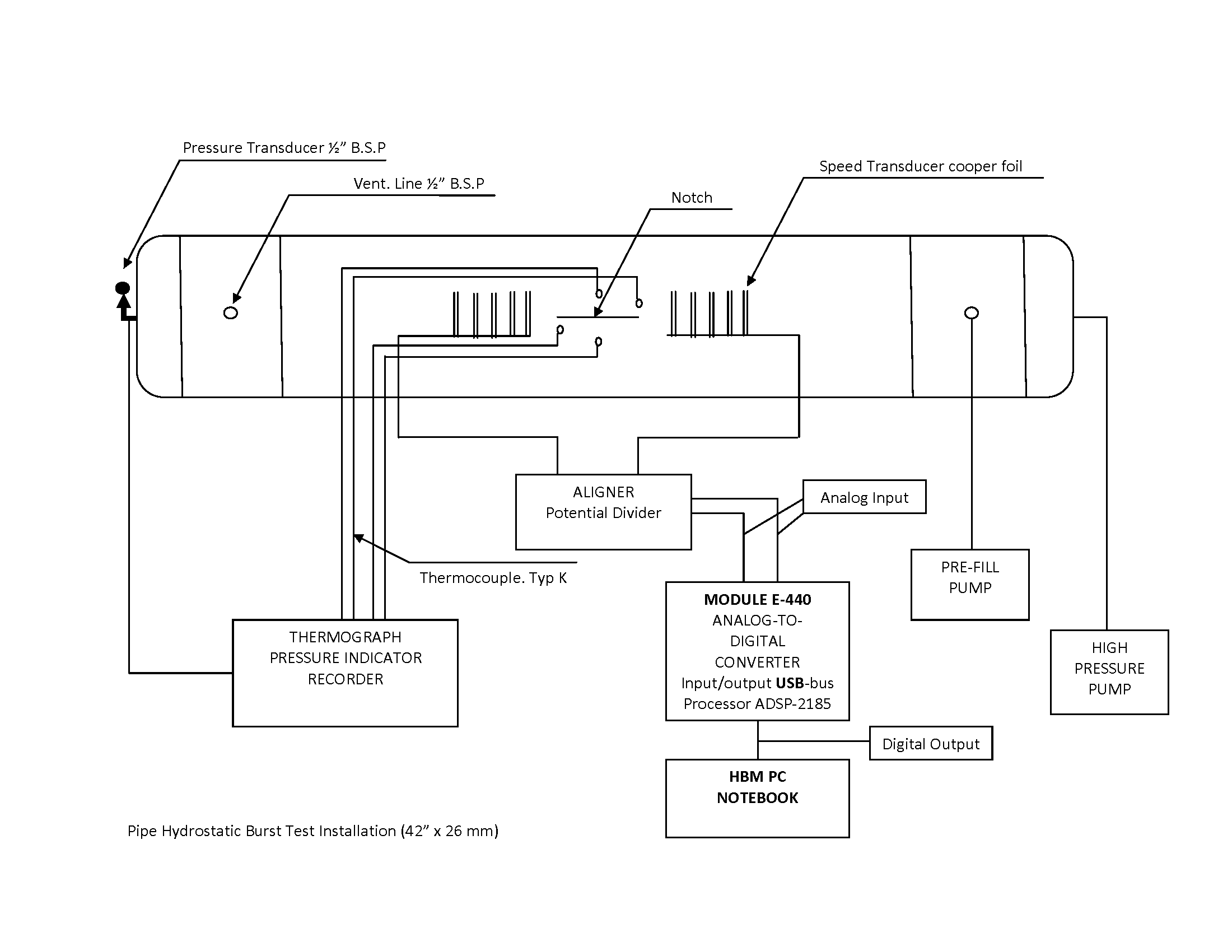
The full-scale burst test is another practical test that is used to determine properties of high grades of steel. This is also a validating test in which a specific material and design condition is used to validate the arrest toughness of the material. A range of conditions are created. Strategically located strain gages record actual conditions of failure. Actual absorbed energy is recorded. The practical applicability of such tests is very useful for steel with yield strength over 80 ksi. A typical arrangement of a burst test is given in Figure 5.
In a typical full-scale fracture propagation test conducted for a client who wanted to use X80 grade of pipe from their stock. The MTR of the five pipes used for the test indicated the average CNV to be 98 ft/lbs, and shear in excess of 90%. Pipe of 40-inch diameter and 0.888-inch wall thickness was used for testing. The test section of three pipes was welded according to a qualified procedure. At both ends of this test section, a 1.5 diameter length of X56 grade pipe section was welded: 1) to facilitate attachment of test system; 2) to learn if low-strength ductile pipe would be able to arrest runaway crack.
The material test reports of 1.25-inch wall thickness X56 pipe indicated that the pipes impact tested and had over 100% shear and average impact value of over 110 ft/lbs. The test media was 96% methane lean gas. The fabricated assembly of five pipe sections was pressurized. The crack occurred in the target middle pipe. At 2,856-psi pressure, the pipe failed corresponding to about 85% SMYS. The crack stopped at the 1.25-inch wall thickness of grade X56. The measured crack speed in the target pipe ranged between 310 and 240 meters per second. The initiated crack propagated to both ends of the test section indicating insufficient toughness in the pipe for its intrinsic ability to arrest the crack in the given test conditions.
In yet another burst test that was carried out by a mill to demonstrate the ductility of API 5L X70 pipe material, a full-scale hydro burst test was carried out on a 42-inch diameter, 1.02-inch (26 mm) thick pipe. The test was done at -7oC (20oF) to -10oC (14oF) temperature.
The pipe was prepared by welding two end sections. The target pipe was in the center. In the target pipe, a notch of 16 mm (0.63-inch) deep and 410 mm (16 inches) long was created to initiate the crack in the pipe. The impact value of the material was 130 J (96 ft/lbs) at -60oC (-76oF) and shear values of 86-88% at -31oC (-24oF) obtained from DWTT.
During pressurization and testing, the strain gages were attached to see the online deformation of the pipe, as indicated in the schematic sketch of the test.
The burst occurred on the target pipe at the location of the notch created to initiate the crack. The burst pressure was recorded as 185 Kgf/Cm2 (2,631 psi). The crack propagated to about 1,114 mm (43.858 inches) and stopped. It may be noted that the length of the crack is about one diameter of the pipe, and the opening of the facture at the widest point was about 155 mm (6.1 inches). The diameter of the pipe was locally expanded to about 100 mm (4 inches), indicating the ductile nature of the fracture.
This test indicates that the steel of the pipe was suitable for resistance to ductile fracture at the given low temperature. The ductility of the material can be assessed by the relatively small length of the propagation and the localized ballooning of material at the fracture location.
The tests and calculations discussed above answer the question we asked at the beginning of the article: What is the required toughness that would arrest the propagation of ductile fracture? This also indicates the most important factor that the required toughness that would arrest the propagation of ductile fracture in a pipe can be achieved by procuring clean steel suitable for the design conditions of the pipe-making project.
Authors
Pankaj Mittal is senior vice president, Corporate Quality & Technical Services, Welspun Pipe Inc. Little Rock, AR.
Ramesh Singh, MS, I Eng, MWeldI, is senior principal engineer, Gulf Interstate Engineering, Houston.

Comments