
March 2010 Vol. 237 No. 3
Features
Managing And Storage Of External Corrosion Direct Assessment Data
External corrosion direct assessment (ECDA) involves a large of amount of data resulting from the associated indirect inspections and direct examinations. It also requires data to even begin with pre-assessment activities.
This article covers the data storage and management considerations of all four ECDA stages as well as enterprise data storage considerations as outlined in the following sections.
ECDA Stage 1
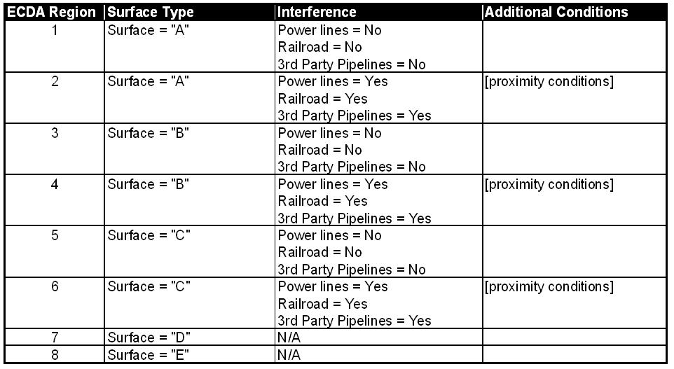
ECDA Stage 1 is pre-assessment data gathering. Prior to gathering data for the pre-assessment stage, establish your criteria for determining ECDA regions (if you don’t already have it captured in internal documentation or work instructions). Then access the amount and condition of data that is available to you as required by your criteria. If your assignment of indirect inspection methods relies on data in addition to ECDA regions, then you should also consider it in this stage. Your ECDA region determination may look something like Table 1.
The ECDA region criteria implies that you should evaluate the condition and availability of surface type as well as the proximity of power lines, railroads and third-party pipelines.
You may also decide to gather data such as soil class, soil resistivity, leak history and CP effectiveness to determine an initial external corrosion rate and likelihood of active external corrosion. If this data is not utilized to determine ECDA regions, it may be better to account for it after ECDA region determination as initial external corrosion rate and likelihood of active external corrosion are attributes of determined ECDA regions.
It is ideal if you can leverage an up-to-date database (perhaps a centrally maintained pipeline GIS) for Stage 1 data gathering, but you may be forced to locate the data from various sources and pull it into one location for your analysis. If some of the required data is not available, you may have to adjust your ECDA region criteria to meet what data you have available.
When collecting Stage 1 data, the most efficient way is to store each data type independently and use “dynamic segmentation” upon analysis. This allows you to minimize the adjustment of segments as you compile the data. Figure 1 explains the dynamic segmentation process.
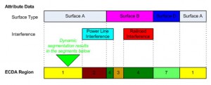
Figure 1: Dynamic Segmentation Example.
If dynamic segmentation is not an option as part of your analysis, you should still try to store each data type independently and manually segment that data as the last step of the Stage 1 data gathering process.
Once you have your ECDA regions determined, it should be a fairly easy step to assign indirect inspection methods. More challenging is the determination of initial external corrosion rate and likelihood of active external corrosion. To do this, you should already have your logic established for determining these values. Your logic should account for using the worst-case values (in the instance that you have both soil class and soil resistivity data for determining initial external corrosion rates for example). At this point, you can “overlay” the data you have available such as soil class, soil resistivity, leak history and CP effectiveness and for each ECDA region, determine the values.
The output of this Stage 1 analysis should be range locations of ECDA regions and assignment of indirect inspection methods and possibly the assignment of values for initial external corrosion rate and likelihood of external corrosion to each ECDA region. As such, one possible table structure could look like Table 2.

Table 2: Example ECDA Region Storage (this is a simplified example for illustration purposes).
ECDA Stage 2
ECDA Stage 2 involves indirect inspection data collection. The indirect inspection data that is utilized in Stage 2 typically comes from various contractors. Often, the format of the data is inconsistent, which leads to subsequent challenges when analyzing. The best strategy is to mandate a specific file type and format in which contractors are to submit indirect inspection data. An XLS or CSV file type is a good choice as it is easy to generate and subsequently use.
The required columns within those files should be specified as well including specifics about the type of data to be stored (integer values, alpha-numeric, validation, etc.). For illustration purposes, an example for CIS data is shown in Table 3.

Table 3: Example CIS File Format.
The same strategy should be employed for all indirect inspection types which requires an understanding of how that data is to be stored in a database.
The method in which the data is collected also has an impact on data storage and alignment. The best approach is to conduct a GPS centerline survey (either separately or as part of one of the indirect inspections). This helps to establish an accurate centerline to which all indirect inspection data (and subsequent excavations) can be referenced. The accuracy of this GPS-surveyed centerline may differ from a GIS centerline (if utilized) which needs to be considered carefully when storing results (covered in section titled “Enterprise Storage Considerations”). It is important to note at this point, however, that the ECDA regions as determined in Stage 1, must be reconciled to GPS-surveyed centerline (i.e. stretched/compressed to properly fit the newly established centerline).
Once available for use, the indirect inspection data should be validated as it is loaded into your database. It’s ideal if you have configurable validation rules as part of your data load application so that you can more readily locate and correct inevitable mistakes in the data.
The indications derived from the various indirect inspection data are typically range values and should be stored to their own table separate from the indirect inspection data (by nature, they are much different). The storage of indications should also include an ability to store severity per indirect inspection method.
ECDA Stage 3
ECDA Stage 3 involves direct examination data collection. Assuming that indications were located and severities assigned in Stage 2, the prioritization of indications is not only important for determining where to do direct examinations, but it also has implications in determining process effectiveness in Stage 4. That priority should be stored per indication. You should also account for additional findings that may impact your determination of process effectiveness (for instance, did you find something that could be considered “immediate”, but it was only considered a “monitored” prior to excavation). These variations should be considered for storage of Stage 3 data to assist the Stage 4 analysis.
However, subsequent direct examinations should be stored in their own table as one direct examination can contain more than one indication. For subsequent process effectiveness purposes, it may be important to also store whether a direct examination was added to the list after initial prioritization.
When conducting direct examinations, there is a tendency to attempt to store all observed data in tables in a database. A better strategy is to strike a balance between what should be stored in a database and what can be attached in the database as reports to the direct examination. The reason for this balance is that it can be expensive – both in terms of data modeling and user interface complexity – to store everything in tables.
Certainly, data to be used in subsequent calculations or as part of the remaining life analysis should be stored in the database (e.g. defect size, findings for process effectiveness). If your process already accounts for the determination of failure pressure in the field (perhaps using a simple RSTRENG spreadsheet) then it may be best to store the results of that calculation rather than the profile measurements of the defect (which could be attached in the database as a report but not in a table specifically designed for profile measurements).
If you are able to leverage a central database or pipeline GIS, you should also consider storing that data which may be used to update that central database (coating condition, soil condition, etc.). In general, the following data (in addition to any repairs made) should be considered to be stored per direct examination whether as part of the database or as an attached report:
- Site information.
- Soil (depth of cover, class, pH readings, MIC indications), soil resistivity).
- Coating (type, condition, presence of holiday, disbondment and MIC).
- Defects (type, measurements, orientation, wall thickness, calculated failure pressures).
Because there can be multiple defects for each direct examination, the defects should have a many-to-one relationship with the direct examination as shown in Figure 2.
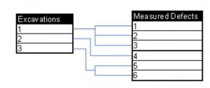
Figure 2: Table Relationship, Excavations and Measured Defects.
Depending on your data capture approach, it could also mean that captured coating and soil data have a similar many-to-one relationship with the direct examination. As such, you should carefully consider your data collection approach prior to determining your excavation data storage requirements.
You should also consider storing whether any found defects should be included or excluded from the remaining life calculation per NACE SP0502 as part of each defect (perhaps as simple as an additional column in that table). This can assist in the post-assessment stage.
ECDA Stage 4
ECDA Stage 4 involves post-assessment. Most of the results of post-assessment are best stored as attributes to the ECDA regions originally determined in Stage 1 (Table 2). This includes onset of corrosion, the analysis results of corrosion rate and peak depth (for remaining life calculation).
The process effectiveness portion of Stage 4 requires data already stored in previous stages. Your logic for determining process effectiveness may affect how you store indications and will certainly affect how you store direct examination results (see previous sections).
The remaining results – remaining life, reassessment interval and process effectiveness – can be stored for the entire project or as part of the ECDA segment.
Enterprise Storage Considerations
As you perhaps already know, there will be a large amount of data that results from an ECDA project. The challenge is to determine what amount of that data to store to a central database or pipeline GIS. The most straightforward method is to load DA results (reassessment interval for the ECDA segment) and perhaps direct-examination data linked to the locations of the excavations. The loading of indirect inspection is also possible as well as the loading of determined indications.
As briefly covered in a previous section, the GPS-surveyed centerline may be more accurate and of different length than the centerline stored in your central database or pipeline GIS (if available). A strategy should be determined on how to account for this discrepancy if you plan to place the results of your DA project into that database. Two options exist:
- Adjust your centerline in the central database or pipeline GIS and upload all results directly.
- Adjust your DA data (i.e. stretch/compress to properly fit the GIS centerline) prior to loading to the central database or pipeline GIS.
Depending on the management of your central database or pipeline GIS, either approach could be valid. If 1 is your better option, then a process should be put in place to ensure that the pipeline GIS centerline is adjusted prior to loading your DA project results. If 2 is your better option, then an adjustment needs to be made to the data prior to loading your DA project results.
Conclusions
The execution of ECDA results in a large amount of different types of data. Prior to starting the endeavor of storing and managing that data, careful design must be employed. The criteria for analyzing that data (region determination, remaining life, process effectiveness) must be fully established before design work starts on the data-storage mechanism. Careful consideration of field collected data – indirect inspections and excavations – and their intended use must also be employed. And finally, a business decision must be made on how to integrate with enterprise data, if available.
Acknowledgement
This article is based on a presentation at the GITA 2009 GIS for Oil & Gas Conference in Houston.
Author
Dana Book, P.E., is engineering manager for GE Oil & Gas- PII Pipeline Solutions. He joined GE in 2003 and is responsible for the Integrity Services Engineering Team which includes software development and customer implementations of PII software solutions. He holds a B.S. degree in civil engineering from the University of Nebraska-Lincoln.

Comments