
July 2010 Vol. 237 No. 7
Features
HDD Solves Pipeline Relocation In Venice Canal
When it became necessary to dredge and deepen the Bacino di Evoluzione No. 3 ship canal in Venice to accommodate larger ships, an existing IES (Italiana Energia e Servizi S.p.A.) oil pipeline crossing the canal had to be relocated.
Before proceeding with the project, IES officials carried out a careful analysis and decided horizontal directional drilling offered the best solution to install the pipeline at depths specified by port authorities. LMR Drilling GmbH was charged to carry out the final design and to realize the HDD. The works were performed during August and September 2009.
Site Location
The site is located in the central part of the Venice lagoon, three miles south of the town of Mestre and three miles west of Venice center itself. The pipeline crosses the Evoluzione 3 Canal and connects Oil Island with the Romagna Pier. The Venice lagoon originated about 6,000 years ago. Originally it was much less extended because the sea water level was substantially lower than today and large areas, now under water, were instead dry lands.
As sea water levels rose, the depositional environment changed from continental conditions, with fluvial and fluvio-glacial transport and sedimentation, to a low energy marine environment.
Due to the environmental changes, two sedimentary complexes are present, even though they are similar as regards the lythological and grain size composition. At the bottom, late-Pleistocene marine deposits are found above the Holocenic lagoon deposits. Both of them consist of silty-sandy-clay soils with low consistency and high vertical and lateral variability. The passage from the former to the latter is marked by a well-defined level called “caranto,” of overconsolidated clay due to drying which represents the paleo-ground formed between the two depositional cycles.
Within the lower depositional complex, many peat layers with pieces of wood are present.
As regards the hydrogeological conditions, no continuous aquiferous is present, due to the high soil variability; only local perching ponds, not connected, can be found. The “caranto” level of high consistency and impermeable material sometimes confines artesian waters.
Geotechnical Characteristics
The geotechnical characterization of the site was based upon specific investigations (boreholes and tests) as the result of geotechnical studies performed in close areas for the Protective Intervention of Venice on behalf of the Venice Water Authority and available information from scientific literature.
As regards the stratigraphy, a high-grain size variability can be noted up to and over the maximum HDD depths, with prevalence of clayey and sandy silts between 130-160 feet. Such variability has repercussions on the geotechnical parameters, as can be noted in the characterization in Figure 1A by Cola and Simonini 1995.
The assessment of the geotechnical parameters, used for the HDD design, is based on results of the tests performed in the boreholes close to the HDD line (S.P.T., Torvane, permeability) and of the tests, both on site and laboratory, carried out for the Protective Intervention of Venice.
Due to the high variability of the encountered soils, no continuous layers with specific geotechnical parameters were found; only a distinction between cohesive and granular soil was made, whose values of the main parameters are listed in Table 1.

Table 1 – Values of the main geotechnical parameters
The “caranto” layer, found at 4 – 8 meter depths, represented by over consolidated clay and silt, has a higher strength resistance with values of undrained cohesion of about 100-200 kPa, (E. Giacomini, 2009).
Difficulties
For design of the HDD crossing, LMR Drilling had to take into account the particular local conditions where the line should be located, both in terms of the serious limitations due to available work areas and of the characteristics of the soils the pipeline route would cross.

General view of the entrance working area.
The entrance area is located on land within the harbor area along the Romagna Pier, where bulk shipping containers are stored. The pier is paved and therefore no digging was allowed, except for a small entry pit. All the area was fenced and drill cuttings were stored in two temporary basins using precast jersey barriers.
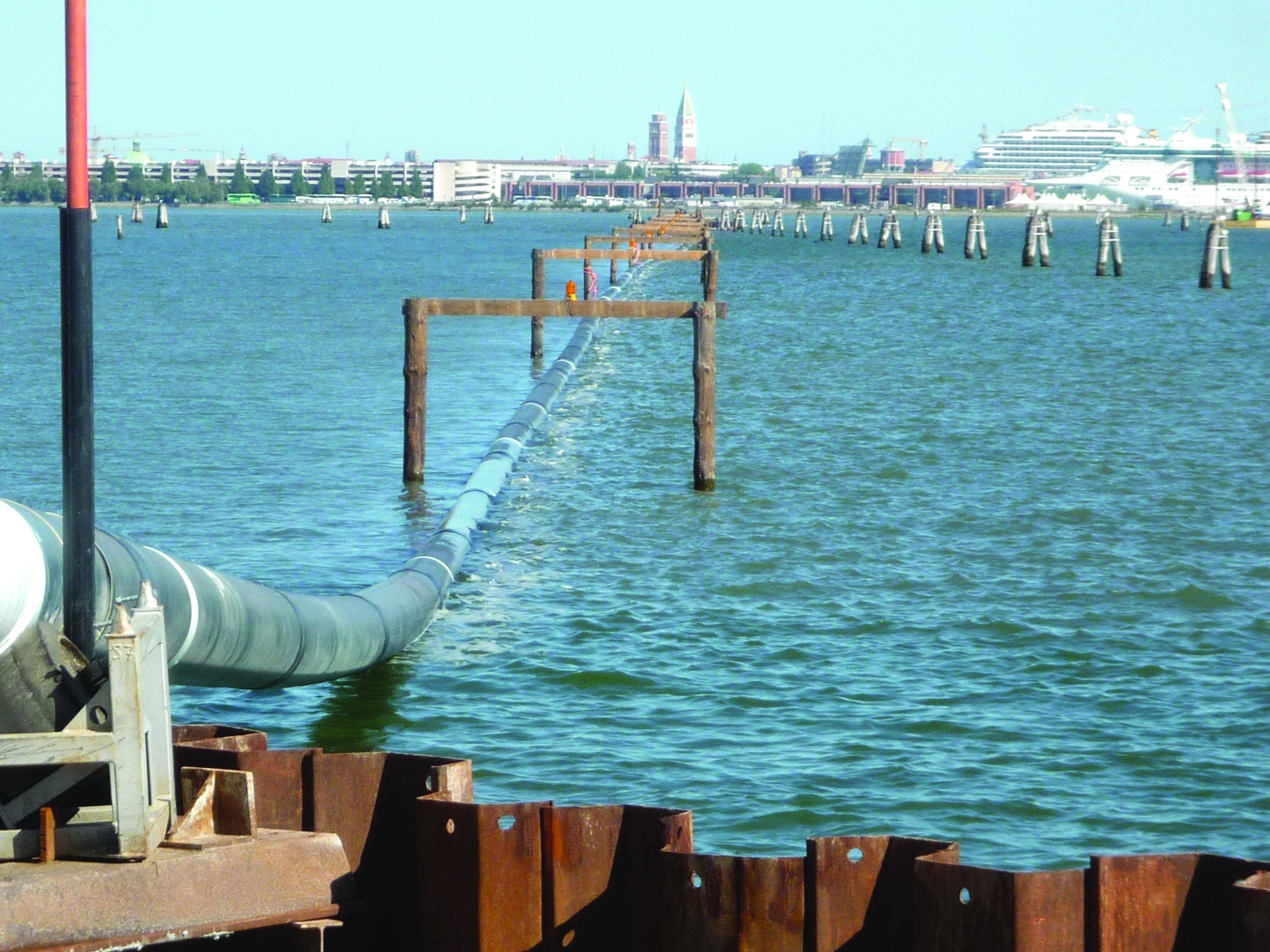
Across the Evoluzione 3 Canal, the exit area for the HDD is located on Oil Island where a large number of oil tanks are located in front of the Romagna Pier. An existing 48-inch oil pipeline, located on the ground close to the exit point, also had to be protected during the over-bend preparation and pullback phase.

Aerial image of the HDD route (by Google Earth).
Due to the existing sheet pile protecting both the pier and the island, and a concrete basin on the island itself, a horizontal curve had to be designed into the drilling profile in order to avoid these structures.
Moreover, the short extent of the island didn’t allow crews to prepare a single pipe string on land. Instead, it was necessary for about two-thirds of the pipe string to be floated on the water, (Photo 2).
As regards the type of soils to cross, they were all of low consistency and density, so that the HDD profile had to be deepened (about 160 feet below the entry level) in order to avoid any break out phenomenon and consequent of possible mud loss in the canal area. A detailed geotechnical study was needed to optimize the correct profile depth as a function of the mud pressure to use while drilling.
Pressure Calculation
During the HDD execution (both pilot, reaming and pullback phase) the mud pressure in the hole is kept higher than in the surrounding soil to keep the hole stable and allow a continuous return flow of cuttings. When the pressure rises above certain values, plastic deformation of the soil will result around the hole. When the pressure is increased beyond this value, the zone with plastic deformation will enlarge as well, inducing soil fracturing and loss of mud circulation.
The calculation consists of the comparison of the limiting pressure (sustainable pressure due to the soil above the drilling line) with the operational pressure needed to progress. The latter necessarily has to be lower than the limiting one.
The limiting pressure was computed using a theoretic approach know as the Delft Formula (H.J. Luger and H.J.A.M. Hergarden, 1988), and based on the analysis of the plastic zone around the hole (cavity expansion theory) as a function of the strength and deformability characteristics of the soil. The operational pressure was assessed as the sum of the hydrostatic mud pressure and the mud pressure loss occurring when it flows back from the drill head up to the exit point, using a Bingham flow model in the annulus.
The results of the analysis verified that no mud loss risk should occur in the canal, (Figure 2). A frac-out could result only in the final section on the island close to the exit, which offered easy access in the event protection or cleanup became necessary.
Tools & Guidance
The following HDD tools were used on the project: 14¾-inch pilot drilling head; drilling rods: 6 5/8-inch by 30 feet; 26-inch reamer; and 22-inch pulling reamer.
Due to the difficulties in transferring mud from the exit to entry area, two different mud treatment units were used.
As regards the guidance system, the presence of steel pipes and deep structures, such as sheet piles, do not allow the use of a magnetic system; thus a gyro system was used, integrated in the very last section by a walkover locator.
Drilling Profile:
• Entry angle 12 degrees;
• Exit angle 12 degrees;
• Descending bend radius 3,280 feet;
• Raising bend radius 1,970 feet;
• Horizontal bend radius 6,560 feet;
• Maximum depth 167 feet;
• Depth under the sea canal 105 feet;
• Drilling length 4,023 feet;
• Horizontal drilling length 3,942 feet.
Pipe Characteristics:
• Pipe diameter 508 mm
• Thickness 9.52 mm
• Steel X 52 (360 N/mm)
• Pipe protection HDPE 3 mm
HDD Execution
The HDD work started by drilling a pilot hole on Aug. 18, 2009. Eight days later the pipe reaming began and the pullback was completed on Sept. 2 with a total work duration of 16 days. The planned timeline was fully respected despite some logistical difficulties such as the need for vessels not only to ferry personnel but also for the transfer of materials, tools and equipment.

Peat and timber pieces being removed.
Even the mud storing and transfer during the pullback phase required careful planning and synchronization of the various operations, due to the particular site location. On the exit side, the mud was temporarily stored in waterproof containers (whose number was limited by the available space of the work area) while a large number of vacuum trucks continuously transported mud to the disposal area.
On the exit side, mud was temporary stored in basins lined with impermeable covers during the pullback operation. From here, it was pumped to a barge and then later transported to the entry site. There were no serious unforeseen occurrences during drilling; however, slowdowns did occur occasionally due to the presence of peat and timber pieces, resulting sometimes in long breaks for filter and separating unit cleaning.

Graphs of speed, push, torque during pilot drilling.
The crossed soils, consisting of thin alternations of silts-clays-sands of low consistency and density, didn’t present difficulties during the drilling progress, but required a careful steering ability in order to maintain the planned profile direction.

The Punch-out exited just 20 inches away from the target.
Conclusions
LMR Drilling GmbH realized the crossing with safety, fully respecting the timeline and overcoming any logistic and operational difficulties by correctly using the directional drilling technique. A proper design of the route and an adequate choice of the drilling tools allowed a precise, speedy and successful crossing of the canal with full satisfaction of the client. Great help was derived through the use of an accurate steering system based on the gyroscope device which allowed correct guidance in the presence of highly magnetic fields. In fact, thanks to the perfect steering and drilling, the pilot punch-out was less than 20 inches from the target peg.

Comments