
April 2010 Vol. 237 No. 4
Features
Autobalance System Developed For Legacy Slow Speed Integral Engines
An automatic, continuous engine pressure balancing system has been installed on a Cooper-Bessemer 10V-250 on the Williams Gas Pipeline (WGP) system. The autobalance system uses permanently installed pressure monitoring that provides pressure information to a continuous feedback control system.
This system uses an electronic fuel balancing valve for fine tuning the fuel delivery to each cylinder to achieve near perfect balance for all operating conditions of the unit.
WGP operates 41 compressor stations from South Texas to New Jersey. Currently 125 out of a total of 307 reciprocating engine-driven compressors in those stations are monitored locally and remotely through an advanced continuous pressure monitoring and diagnostic system. This continuous pressure monitoring system utilizes crankshaft-referenced dynamic pressure measurement and advanced automated software analysis of power cylinders and compressor cylinder ends to accurately and reliably detect malfunctions, provide easily understood diagnostic messaging, and enable unit-to-unit economic performance comparisons over the WGP wide area network (WAN).
Today, the company’s engines are operating in a different era than when they were first installed 50 plus years ago. In the beginning, most of the pipeline industry had operators in the compressor buildings 24 hours a day, 7 days a week, and 365 days out of the year collecting readings and watching over the equipment. Detonation is a way the engine “communicates” that it has a problem and is in need of attention. When an engine began to detonate, the operator would balance the engine, reduce the load, or make other operating corrections to eliminate the detonation. Ultimately this may have led to stopping the engine. Today, automation is in control of operating the engines, most if not all of the operators are gone and the majority of the compressor stations are unattended. For the remaining WGP reciprocating engine fleet without continuous pressure monitoring we have no way of knowing if the engines are detonating unless someone is in the building.
Project Development
WGP has historically determined that the peak-firing pressure (PFP) method provides the best measure of engine balance. There are two basic requirements for proper peak-firing pressure balance: accurate peak-firing pressure and control of fuel delivery system to each cylinder.
WGP and Windrock recognized that the accurate peak-firing pressure provided by the power cylinder continuous pressure monitoring systems would satisfy the first requirement. With an operating history of approximately five years, the continuous pressure monitoring power cylinder pressure transducers have demonstrated good reliability and the online calibration capability has maintained the required accuracy.
Since accurate peak-firing pressure available from the Windrock continuous pressure monitoring system would satisfy the first requirement of this method of engine balance, the two companies agreed to participate in a developmental project which involved power cylinder autobalancing of a legacy two-cycle engine. The primary goal of this project would be the development of an electronic replacement for the manual balancing valve to satisfy the second balance requirement. Kiene Diesel was selected to provide expertise in designing and producing the electronically controlled balancing valve.
A Cooper Bessemer 10V-250 engine was chosen for the project based on the following factors: it is an engine with stable combustion characteristics, it already had the power cylinder pressure sensors and data acquisition board installed, and all other engines at this facility had been retrofitted with Enginuity’s HPFI? system which included autobalance capability
The Need For Autobalance
There has been much written about the correct procedures for balancing the power cylinders of large-bore slow-speed engines. In order to get the best performance as well as lowest operating costs from an engine, it must be balanced correctly on a regular basis. Since many factors can cause an engine to go out of balance, balancing frequently is desirable, but must be weighed against manpower requirements. By utilizing a good balancing program, the operating and repair cost can be reduced considerably.
An unbalanced engine can cause any of the following conditions: detonation, lower load carrying capability, increased emissions, increased fuel consumption, combustion instability, cylinder wear, piston ring wear, piston ring blow-by, carbon buildup in the ports, excessive frame vibration, foundation issues, bearing failures, and a general increase of engine and support equipment wear.
Manually balancing an engine requires the following labor-intensive steps: collect pressure for each power cylinder, analyze collected pressure data and determine which cylinder requires adjustment, make adjustment on identified cylinder(s), and repeat above steps until desired level of engine balance is achieved.
A good manual power cylinder load balance on a 16 cylinder engine can require two to four man-hours to accomplish.
Autobalance System Design Features
A schematic overview of the complete autobalance system is shown in Figure 1. The three topics and their related components include: continuous cylinder pressure monitoring system topic with related components: pressure sensor on each cylinder, E-Guard data acquisition system and magnetic pickup(s) on flywheel; autobalance control system topic with related components: automatic fuel adjustment valve on each cylinder, autobalance board and firmware; and combustion diagnostics topic with related components: combustion statistics, waveform analysis and interface to programmable logic controller.
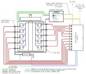
Figure 1: Schematic of autobalance system.
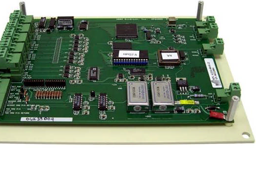
In the cylinder pressure monitoring system currently installed, pressure transducers permanently mounted on the power cylinders (Figure 2) provide the primary measurement input for the continuous pressure monitoring system. The pressure sensor is a piezo-electric type supplied by PCB. Continuous combustion pressure data is collected from each cylinder by the E-Guard (Figure 3) that is housed locally in the unit control panel. E-Guard is a data acquisition system that provides crank-angle referenced pressure waveforms from each pressure sensor and calculates peak-pressure and peak-angle statistics for all power cylinders. Multi-ported pressure indicator valves, supplied by Keine, allow for connection of portable analyzers or connection of a reference pressure sensor for online calibration of the pressure sensors. Data gathered by this system includes: mean peak pressure, standard deviation of peak pressure, mean peak pressure angle, standard deviation of peak pressure angle, compression pressure, percent non-combustion cycles, percent pre-combustion cycles, percent over-pressure cycles, and raw waveforms for manual analysis.
This data is calculated in real time for all combustion cylinders on the engine. The data is available to the autobalance controller via a communications link and also is available to the unit programmable logic controller via Modbus communication.
A key feature of the E-Guard system is the ability to determine problems occurring in the pressure sensors that would invalidate the peak pressure data. Several tests such as comparing compression pressure of each cylinder and evaluating the shape of the combustion waveform at key points are used to determine the health of each pressure sensor. If a sensor problem is determined by the firmware, it is noted in the status value associated with each sensor.

Figure 2: Pressure sensor and indicator valve.
Project Developmental Tasks
After the basic architectural design (Figure 1) was established for the autobalance project, the following tasks were identified: map engine – establish baseline engine operating parameters, develop and test automatic balancing valve, develop autobalance hardware, develop balancing methodology, develop configuration and monitoring software, and install and test system. The entire development project took about one year to complete. To conserve space, this article will conclude by focusing on installation, testing and conclusions.
Installation And Testing
Once all the development tasks were completed, a full autobalance system was deployed on the 10V-250 engine (Figure 4 (was Figure 17) and Figure 5 (was Figure 18). The unit was already equipped with the Windrock E-Guard continuous engine peak-firing pressure monitoring system. Station personnel installed a balancing valve on each power cylinder, installed conduit and wiring, installed the autobalance control board, and interfaced all the systems together.
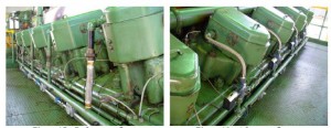
Figures 4 (left) and 5: Before and after retrofit.
Testing was performed with the engine off to make sure that all the valves were under control and communications were active. All the valves were positioned at 50% of travel and the engine started. Before autobalance mode was enabled, tests in manual mode were made to ensure that the system performed as expected. In manual mode, testing was performed to determine the optimum step change size, change interval, and limits of valve motion.
Once this testing was completed, limited times of autobalance under close user supervision were attempted. During this time, days were spent manipulating engine load, speed, and balancing valve positions to observe the behavior of the autobalance logic when faced with various challenges. Initially, the system was disabled when station personnel were not present. Gradually, as confidence in the system grew, the system was left in autobalance mode and unmanned continuous operation. Currently, the autobalance system remains in continuous operation and is keeping the unit at the desired balance.
The engine was intentionally unbalanced before the autobalance logic was enabled for the first test, as shown below in Figure 6. After only 22 minutes the autobalance system was able to achieve the required balance as shown in Figure 7.

Figure 6: Before autobalance enabled.
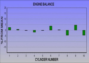
Figure 7: After autobalance enabled.
Balancing peak-firing pressure distributes the load equally across all cylinders providing the following benefits:
- Automatically balances each cylinder to +/- 5% of the engine average peak-firing pressure.
- Lower fuel usage.
- Lower maintenance cost.
- Continuous protection from–overloaded (overpressure) cylinder, detonation, pre-ignition, misfiring or dead cylinder, unstable combustion, low compression pressures and erratic peak pressure angle.
- Maintains normal emissions for all operating conditions–speed, load, fuel Btu content, and ambient temperature.
- Engine combustion diagnostics and customer support can be performed remotely via the Internet.
Project Summary
The system has proven to be capable of achieving desired balance under all conditions encountered.
While monitoring the system it has been observed that when the engine is well balanced, peak-firing pressure statistics tend to be tighter, and combustion is more stable.
For test purposes, when the engine was intentionally taken out of balance on the high side, NOx emissions were demonstrated to increase by 20% or more. When the engine was intentionally taken out of balance on the low side, NOx emissions did not indicate a significant change.
Strong safety mechanisms were designed into the system to prevent a runaway condition of the balancing valves. Several criteria will take the system out of autobalance mode in the event that any part of the system malfunctions. This includes strong pressure sensor diagnostics, positive valve movement indication, and limits on cylinder over-pressure. The programmable logic controller was programmed to shut down the unit in the event of cylinder over-pressure.
The first generation of the valve drive mechanics had two optical switches to indicate close to fully open and closed. The second generation incorporated the same optical switches but they were repositioned to indicate the movement of the stepper motor. This proved to be a more successful approach for the controller to keep track of the valve position. In the first generation valve, if a failure occurred and the motor did not turn, the controller had no feedback to indicate this condition.
An early concern was that we had too much gas volume between the balance valve and the fuel injection valve because the balancing valve was located two feet from the fuel injection valve. This proved not to be a problem at all. Good balance control was obtainable with the balancing valve located next to the fuel supply rail. This location proved to be much easier to deal with during installation.
One unresolved on-going issue was the malfunctioning of one valve channel about twice monthly. Possible causes were wiring, shielding, or poor solder joints. However, when this happened, the autobalance system disabled the autobalance mode, and the unit continued to operate in manual balance mode. Shortly after the paper on which this article is based was presented, some changes were made to the wiring harness and valve limit switches. Since that work was performed, no malfunctions have been experienced.
After completing developmental work on the 10V-250 engine, WGP and Windrock have since installed the autobalance system on a Clark HBA-8T engine. With the exception of the physical size of the balancing valve and valve trim selection, it was basically a plug and play installation. Even with the combustion differences between the two engine types, the balancing algorithms are working effectively on this engine, which is known to be difficult to balance using traditional manual methods.
The size of the valve had to be increased to give a larger flow cross-section and lower pressure drop due to the lower governor fuel pressure in order to maintain an adequate pressure to the fuel injection valve. On this engine, an average valve position of 70% was needed to maintain pressure at full load. A valve with an equal percentage flow characteristic was chosen. This solution was a compromise, but the area in which the valve normally operated was adequately linear. This proved to be a successful compromise. Any valve non-linearity can be accounted for in digital signal processing on the autobalance board so the control loop will ultimately be linear.
The second generation installation has only recently been completed. It is currently being monitored by WGP and Windrock to determine the overall effects in all areas of operation efficiency.
Conclusion
When mechanical conditions arise and cause combustion problems that impact the operation of the unit, immediate feedback of the problem is available to the user so that the proper remedial action can be taken. If the engine is capable of meeting normal emissions limits at optimum balance, this system should make it possible for the operator to have a high degree of confidence that the engine is within normal emissions limits during all operating conditions.
The development process has produced a system that is successful in its purpose of continuously keeping a pipeline engine in balance. The system has proven to be economical, easily installed, and user-friendly.
Acknowledgment
Based on a more detailed paper presented at the 2009 Gas Machinery Conference in Atlanta, GA.
About the authors
Noah Dixon is senior technical specialist with Williams Gas Pipeline. E-mail: noah.h.dixon@williams.com.
Bruce Howerton is senior compressor engineer with Williams Gas Pipeline.
David Williams is director of optimization for Williams Gas Pipeline.
Edward Flanagan is director of engineering for Windrock, Inc.

Comments