
May 2020, Vol. 247, No. 5
Features
For Inspection and Pressure, How Low Can the Gathering Sector Go?
By Zachary Farrell, C.E.T., ROSEN
As natural gas assets are beginning to age, there is a larger need for integrity solutions in this area. The challenge with these assets is that they often operate at lower pressures, which can make running a conventional inline inspection tool difficult.
When planning an inspection, the most common question in the gathering sector is, “At how low of a pressure can you run?” The answer to this question is often dependent on the size of the pipeline and the number of fittings and bends in the pipeline. Typically, however, it is for a line that is 8 inches (203 mm) or less in diameter.
Increasing pressure on a pipeline with normal production is not always possible, and adding supplemental natural gas or nitrogen is often cost-prohibitive for most operators. This has created a need for conventional inline inspection tools with more compliant specifications.
ROSEN offers compact, low-pressure-capable tools with the ability to go as low as 261 psi (1,800 kilopascals [kPa] [18 bar]) of line pressure, offering a solution from 6 to 20 inches (152 to 508 mm).
Tight Bends
The main challenges addressed in this article are natural gas pipelines with a diameter of 6 to 8 inches and a standard operating pressure of 363 psi (2,500 kPa [25 bar]) or less. The pipelines in this article are 15.5 miles (25 km) or less in length and often have multiple areas of heavy wall thickness and tight radius bends.
Previous inspections were completed by increasing pressure with supplemental gas or by cutting the line into sections and tethering with a bidirectional tool. Running standard free-swimming inspection tools has resulted in overspeed or stuck tools due to pipeline operating conditions.
In most of the lines inspected with 363 psi or less, line pressure will have an effect on velocity, since the tool is passing through tight radius bends (3.0D or less). There is not enough head pressure in the pipeline to act as a brake for the inline inspection tool, which results in a loss of useable data. The standard MFL-A tool will need to operate at a maximum of 16.4 feet/second (5.0 meters/second), with an ideal range of less than 9.8 feet/second (3.0 meters/second).
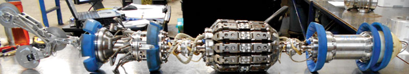
Our solution: Conventional MFL-A, caliper and XYZ (high-resolution mapping) technologies built into a smaller, more compact form factor with high compliance and less weight.
Combining MFL-A/MD and XYZ technologies into one tool has been used for a number of years in a fast turnaround application with a robust design and small form factor. Coupled with rechargeable batteries and hydrogen sulfide resistance, the combined tools are an ideal fit for this environment.
The combination of MFL-A/MD and XYZ technologies into a 6-inch tool makes for a compact design using a multiple-spring-mounted MFL body and a caliper body that contains the inertial mapping unit. The pull unit of the tool also houses the battery.
The 8- to 20-inch tools combining MFL-A/MD with XYZ technologies have a compact design using a lower-friction MFL unit with wheels on the magnet units and spring-mounted MFL-A carriers. The caliper body houses the inertial mapping unit, including all of the tool’s electronics, and the front drive unit of the tool houses the battery as well.
Both of the tools mentioned, along with the rest of the upstream diagnostics fleet, can also operate as standalone MFL-A or standalone caliper tools.
In addition to the tools themselves, reporting timelines have been decreased, which is a major focus of the upstream market. Standard reporting timelines are less than 30 days, with the majority of reports sent within 14 calendar days.
Case Studies
Two separate case studies show inspection tool velocity with pipeline operating pressures of 363 psi or less. The lines could not be taken out of service for a tethered inspection, and it was too cost-prohibitive to use any supplemental gas flow.
Both of the lines in question had multiple locations where 1.5D heavy wall fittings were present, and both had multiple aboveground riser locations. Both inspections required the use of a tool combining MFL-A/MD and XYZ technologies.
The gas flow of the two pipelines could be manipulated manually from the launcher side of the pipeline. There were no major modifications made to either of the tools before the run to perform the service, and no data below have been manipulated. The tools did not suffer any damage during the inspections and recorded within thresholds.
In both cases, the final reports were sent within a 14-day timeframe from the inspection, and all findings were verified by the client.
Case Study 1: An operator in northwestern Alberta, Canada, asked ROSEN to inspect an 8-inch sour natural gas line with a maximum allowable operating pressure of 464 psi (3,200 kPa [32 bar]). With a length of 15.5 mile, it included multiple risers with 1.5D 90-degree bends.
After a successful gauging survey was completed, the minimum inner diameter of the pipeline was recorded at 7.5 inches (190 mm), which is within the acceptable range of the combined tool’s passage capabilities.
The pipeline parameters during the inspection would specify a maximum pressure of 290 psi (2,000 kPa [20 bar]) and a flow rate of 39.6 million gallons per day (150 e3m3/day), which equates to a gas velocity of 7.2 feet per second (2.2 meters/second).
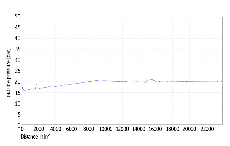
A combination of MFL-A/XT and XYZ technologies was used for this inspection. The tool was also equipped for an external pressure sensor to verify that the line parameters of 290 psi were met. As seen below, the pipeline was within the range for the duration of the inspection, with a maximum line pressure of 305 psi (2,100 kPa [21 bar]) at 50,853 feet (15,500 meters).
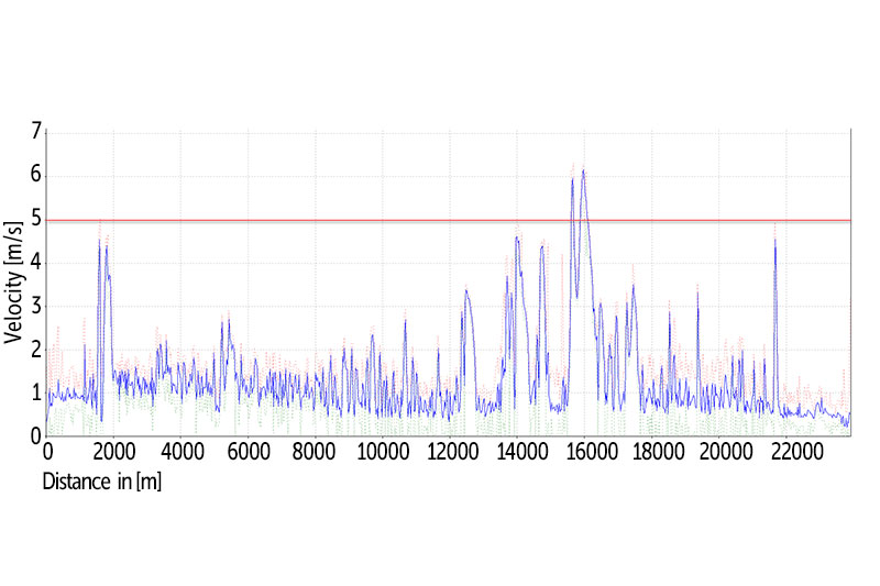
The tool was within its standard 0 to 16.4 feet/second velocity range for 98% of the pipeline, with the majority being under 9.8 feet/second. There is an area at roughly 52,493 feet (16,000 meters), which was over the acceptable velocity due to a riser section where the tool needed the increased pressure to pass through.
Closer to the end of the inspection, the velocity was increasing due to the gas flow being controlled from the launcher valve only. Figure 3 illustrates a capture of the tool velocity, with the red line showing the maximum velocity capabilities.
All of the data collected by the tool were evaluated; the client formally accepted the run, and verification digs were completed.
Case Study 2: An operator in northeastern British Columbia asked ROSEN to inspect a 6-inch sour natural gas line with a maximum allowable operating pressure of 1,400 psi (9,650 kPa [96.5 bar]).
This line was 13 miles (22 km) long and included multiple risers with 1.5D 90-degree bends. After a successful gauging survey was completed, the minimum inner diameter of the pipeline was recorded at 5.5 inches (140 mm), which is within the acceptable range of the combination tool’s passage capabilities.
The pipeline parameters during the inspection would specify a maximum pressure of 363 psi and a flow rate of 26.4 million gallons per day (100 e3m3/day), which equates to a gas velocity of 6.9 feet/second (2.1 meters per second).
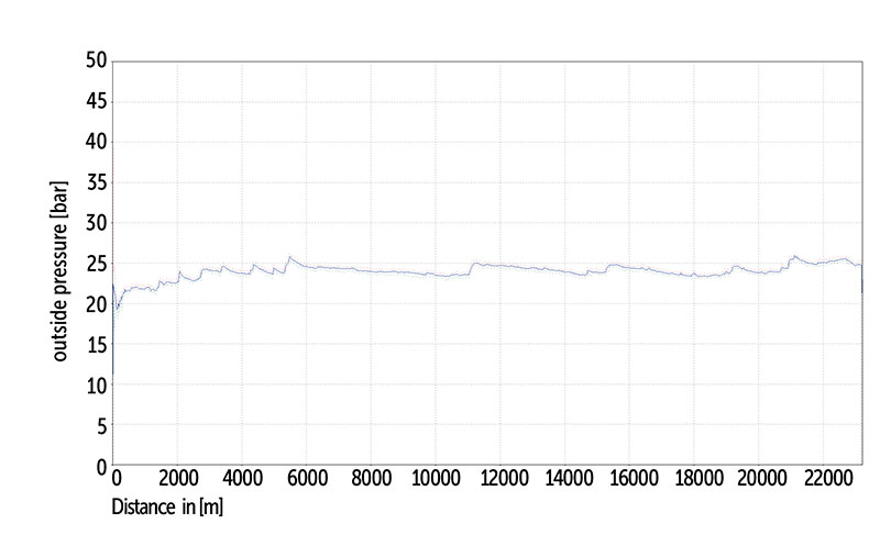
For this inspection, we utilized a 6-inch tool combining MFL-A/MD and XYZ technologies, which we equipped with an external pressure and temperature sensor used for verification purposes. The tool recorded an internal pipeline pressure around the 363-psi mark for the duration of the survey (Figure 4).
During the inspection, the tool was within its standard 0 to 16.4 feet/second velocity range for 99.7%t of the pipeline, with the majority being under 9.8 feet/second. The tool behavior was similar for the duration of the line, with one exception being a riser near the receiver of the pipeline where it briefly reached over 16.4 feet/second. Below is a capture of the tool velocity, with the red line showing the maximum velocity capabilities.
All the data collected by the tool were evaluated; the client formally accepted the run, and verification digs were completed.
Conclusion
After multiple inspections with low operating pressure and a growing database of tool behavior based on various conditions, ROSEN can confidently inspect lines at pressures as low as 261 psi with standard inline inspection tools. Constant improvements to the inspection tools will help push the minimum pressure threshold even lower.
With the growing need for solutions in the gathering market, and in addition to the other services offered by ROSEN, the Upstream Diagnostics Service is a proactive approach to low-pressure inspections, offering full MFL-A, caliper and XYZ reporting.


Comments