
December 2016, Vol. 243, No. 12
Features
Hardness Tester Targets Inspection of Unpiggable Pipelines

The Northeast Gas Association (NGA) and the U.S. Department of Transportation (DOT) have joined forces to co-fund development of a hardness tester module for integration on the Explorer series of robotic platforms, developed for inspection of unpiggable natural gas pipelines.
The resulting hardness tester, built by Toronto, CA-based Invodane Engineering, has been qualified as per portable hardness tester standards and has been integrated on the Explorer X20/26 robot, offering the gas industry a valuable new tool to characterize its pipelines.
Explorer (Figure 1) is an untethered, remotely controlled, self-powered robotic tool designed to inspect unpiggable natural gas pipelines under live pipeline conditions in pipe sizes from 6-to-36 inches. These robots use cameras and magnetic flux leakage (MFL) sensors to carry out visual inspection and measure metal loss in the pipe due to corrosion.
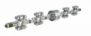
The technology, commercially available since 2012, has demonstrated its ability to inspect pipe segments with features such as vertical segments, short radius bends, 90-degree mitered bends and even plug valves, under flow or no-flow conditions. The Explorer robots can navigate pipelines with a bore reduction up to 75% of outer diameter and a maximum pressure of 750 psig.
These robots are bi-directional and travel at a speed of up to 20 feet per minute. Inspections are performed under live pipeline conditions without the need to shut down or reduce gas flow. The robot is launched into and retrieved from a pipeline through a hot-tap fitting.
There is no need for pre-built infrastructure, such as a trap, for launching and receiving. Explorer provides live video images of the pipeline and integrity data. Video imagery and integrity data acquired by Explorer robots is analyzed with proprietary software. In the past five years, Invodane and NGA have also partnered to develop additional sensing and operational capabilities to offer a wider range of unpiggable pipeline inspection services through Pipetel Technologies.
In response to the San Bruno incident of 2010, PHMSA published the draft integrity verification process (IVP) in the summer of 2013 that required all pipeline operators in the U.S. to document the basis used for establishing a pipeline’s maximum allowable operating pressure (MAOP). In the absence of proper material documentation, testing is now needed to establish a pipeline’s MAOP.
The typical way of obtaining material properties is by cutting out a coupon from the pipeline and carrying out direct material properties tests in the laboratory. However, obtaining a coupon from an in-service pipeline poses certain challenges. Other methods exist, such as hydro-testing and in-situ materials characterization, all having advantages and disadvantages. Their main disadvantage is related to the need to have multiple excavations and multiple access points to the pipeline, thus disrupting the coating.
However, the use of in-situ and inline non-destructive techniques, based on hardness measurements, does not have this major disadvantage and emerges as a desirable solution in many applications. With the ability to carry out an inline inspection, there is only a need for a single excavation and single access point into the pipeline, while numerous tests can be carried inside the pipe at different locations over relatively long distances.
Portable hardness testers exist and are a well-established technology, governed by ASME, CRTD 91, Applications Guide for Determining the Yield Strength of In-Service Pipe by Hardness Evaluation, 2009, which specifies accuracy standards and a process for using these testers in the field.
The Rockwell B hardness test method was selected for use in this tool, having clear advantages over other methods in this operating environment. Following the determination of the pipeline locations to be tested, this process basically consists of a pipeline surface cleaning step and a measurement-taking step.
The determination of measurement sites includes ensuring both end and middle of pipe sections are sampled, and eliminating the possibility of dent, metal loss or presence of a seam weld at the measurement site. It also ensures wall thickness greater than 0.250 of an inch. Surface preparation for a direct Rockwell B measurement requires the prepped surface have no more than 0.010 of an inch of material removed, thus, the system was designed to sand using a coarse grit sandpaper (60, for example) and polish with a finer grit (80-200).
The sampling is done to the Rockwell B standard (ASTM E18), which specifies the load profile, indenter type, indenter size, spacing between sampling points, etc. The hardness value is calculated in real time, while a camera provides direct visual verification of indentation, and the criteria listed in CRTD, Vol. 91 are used for accepting or rejecting readings.
Based on all of these requirements, a module was designed to carry such a surface preparation system and a measurement-taking system. The module is placed on Explorer where the axial MFL sensor module is typically located, such as in the middle of the robot.
The module was designed for launch under live conditions, deployed in a pipeline – able to negotiate long- and short-radius bends, mitered bends and tees – preparing the surface for measurements and taking measurements. Given the large market for the 20-26-inch pipelines, the first unit was designed and built for the Explorer 20/26 robot. Again, the process of obtaining the data is consistent with ASME CRTD 91.
The hardness tester module can be positioned on any part of the perimeter of the pipeline. The module is basically made of a drum, able to be actuated parallel to the axis of pipe as well as rotated, that contains surface preparation and indentation carriages that are moved into position in order to carry out the hardness measurements. Another actuator clamps the sensing section to the pipe wall.
The position for the measurement may be anywhere along the perimeter of the pipe, but the three o’clock and nine o’clock positions are best-suited to minimize interference from any debris in the pipe. The cleaning carriage is first moved into place to clean and polish the surface, followed by the measurement carriage that is moved into place to carry out the Rockwell B measurement.
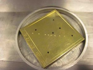
The accuracy of the hardness tester was established using standard calibration blocks (Figure 2) in the range of 60-100 HRBW, while the functionality of the hardness tester module was extensively tested in the laboratory prior to testing under field conditions at the NYSEARCH-operated underground test loop in Johnson City, NY in September. The test loop contains various pipeline features and configurations at diameters of 20 and 12 inches.
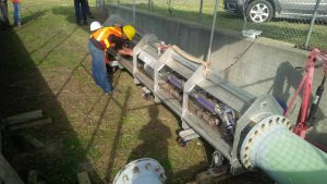
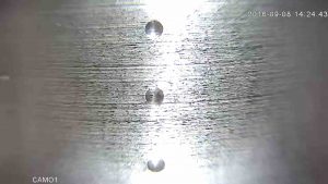
The section was 345-foot-long, containing multiple swept bends. The robot was launched into the 20-foot pipeline (Figure 3) and took measurements at multiple locations while negotiating a number of back-to-back 45-degree bends and a 90-degree bend. The sanding carriage was deployed first (Figure 4) to prepare the surface, followed by the measurement carriage. A dedicated camera verified the indentations and proper spacing (Figure 5).

No issues emerged with the operation of the robot or the tool. The field testing verified what we already learned in the laboratory testing – that good results can be achieved in terms of accuracy, repeatability and error, if the surface preparation is done properly.
A coupon was taken from the pipeline network during the field testing. The coupon was tested at a certified laboratory by a commercial portable hardness tester and the Explorer hardness tester (Table 1); the hardness tester predicts the laboratory obtained values within 1.2%, well within the limits specified by CRTD, Vol-91.
The hardness tester will be available through Pipetel Technologies for commercial deployment in the near future.
Table 1: Sample measurements using various testers.
| Method | Surface preparation | Result [HRBW] | |
| 1 | Laboratory | Polished (200 grit) | 86 ± 1 |
| 2 | Commercial portable tester | Polished (200 grit) | 85 ± 1 |
| 3 | Explorer module tester | Polished (200 grit) | 87 ± 1 |

Authors: Paul Laursen is the founder of InvoDane Engineering. He also founded Pipetel Technologies, a gas pipeline inspection service company created to use state-of-the-art robotic technology developed by InvoDane Engineering. Prior to founding InvoDane, he worked for a leading pipeline inspection/integrity services company. Laursen has a BS degree in Mechanical Engineering from Sonderborg Teknikum in Denmark, and a MS in physics from Queen’s University in Canada.
Dr. George Vradis is a senior technology manager at NYSEARCH, the R&D organization within the Northeast Gas Association. He has managed NYSEARCH’s projects related to pipeline integrity and robotic inspection since 2000 in addition to other projects related to advanced sensors and materials. He holds a Ph.D. degree from New York University and is the recipient of AGA’s 2008 Gas Industry Research Award.

Comments