
Buried Pipe Failures Dependent on Soil Stiffness, Too
This is an excerpt of the article. The full article can be found here.
Performance limits and potential failures must be identified for buried pipe design. Chief among those are excessive deformations of the pipe, wall buckling and collapse.
Maximum allowable pipe deflection is usually not determined by structural failure but by conditions such as clearance for pipe-cleaning equipment, special sections, and pipe appurtenances (attachments). Pipeline designers classify pipes as “flexible” or “rigid,” depending on how they perform after installation.
Flexible pipe can move, or deflect, under loads without structural damage, while rigid pipes cannot deflect significantly without structural distress, such as cracking. From the standpoint of rigidity, pipes were classified by Marston in 1930:
Rigid conduits: The cross-sectional shapes cannot be distorted sufficiently to change the vertical or horizontal dimensions more than 0.1% without causing materially injurious cracks.
Semi-rigid conduits: The cross-sectional shapes can be distorted sufficiently to change the vertical or horizontal dimensions more than 0.1%, but not more than 3% without causing materially injurious cracks.
Flexible conduits: The cross-sectional shapes can be distorted sufficiently to change the vertical or horizontal dimensions more than 3% before causing materially injurious cracks.
In reality, the behavior of a buried pipeline will depend on how its stiffness compares with the stiffness of the soil in which it is to be buried. The soil-pipe system is statically indeterminate. As such, the interface pressure between the soil and pipe cannot be calculated by statics alone.
As soil and surface loads are placed over a buried pipe, the ring tends to deflect – primarily into an ellipse with a decrease in vertical diameter and an almost equal (slightly less) increase in horizontal diameter. The increase in horizontal diameter develops lateral soil support which increases the load-carrying capacity of the pipe. The decrease in vertical diameter partially relieves the ring of load since the soil above the pipe takes more of the load in arching action over the pipe.
Soil-Pipe System
The amount of deflection induced by installation that will occur in any buried pipe depends on three factors: pipe stiffness, soil stiffness, and earth load and surface load due to construction equipment.
Measurements made by Marston and Spangler equations reveal the load on a flexible pipe is substantially less than that on a rigid pipe. The level of lateral earth load also depends on the nature of the backfill and its level of compaction, as well as the stiffness of the side walls of a trench, if the pipe sits in a trench rather than in an embankment fill.
Therefore, it should be readily appreciated that the backfill and its construction are vital to the performance of a flexible pipe. Unfortunately, designers have placed too much attention on the structural properties of the pipe rather than on the soil.
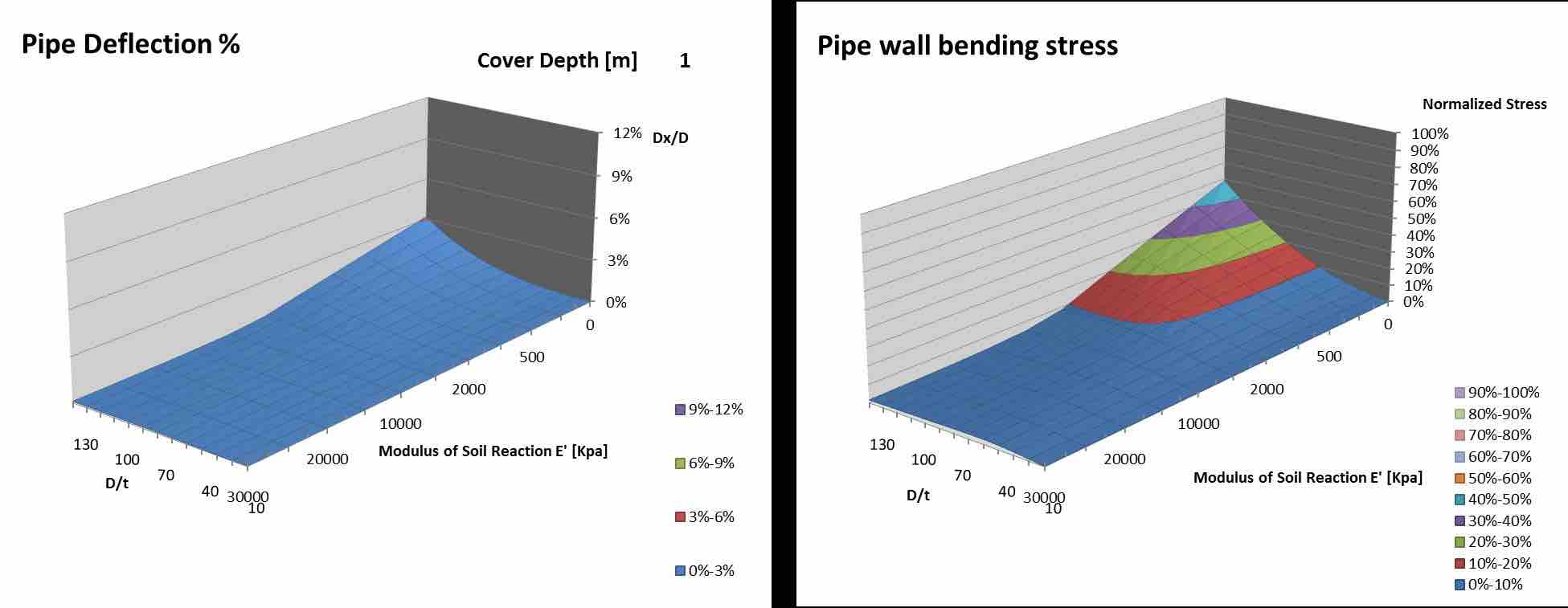
There are many pertinent variables in the complex interaction of pipe and soil. For pipes, one widely recognized variable is pipe flexibility, D/t, which is an inverse form of pipe stiffness, EI/D3, and may be used for analyses involving pipe stiffness of plain steel pipe (no mortar linings or coatings).
Pipe flexibility (D/t) normally ranges between 30 and 100 for oil and gas onshore pipelines. Another common variable is pipe deflection, Dx/D. For soil, the most pertinent variables are the friction angle f and the vertical strain of sidefill embedment, e. An approximation of strain is given by e = s/E’ where s is the vertical soil stress, and E’ is the soil stiffness modulus.
Soil modulus is not a modulus of elasticity and is not a constant. It is often found, approximately, as the slope of a secant to the stress-strain diagram from laboratory compression tests. The confined compression test is conservative since the laboratory sample is subject to a confining pressure and compressed vertically.
Sidefill soil, on the opposite, is compressed vertically, compressed horizontally (radially) and confined longitudinally (biaxial compression) for which the compression (vertical strain) is less than it is for confined compression tests. To define if the behavior of a pipe is flexible or rigid, it is convenient to consider the stiffness ratio Rs as the ratio between soil stiffness and pipe stiffness:
Rs = E’ / (EI/D3) = E’D3/EI
Where:
E’ is the soil stiffness modulus of the soil (slope of a secant on the stress strain diagram);
EI/D3 = E/12(D/t)3 is the pipe stiffness, where I is the transverse moment of inertia per unit length of individual pipe wall components.
Soil stiffness E’ can vary from 100 kPa for damped soil to 50-100 Mpa for well-compacted, coarse-grained soil. Pipe stiffness EI/D3 is inversely related to pipe flexibility D/t and reduces progressively to zero for high D/t values. Usually pipe stiffness contributes significant resistance to pipe deflection if Rs is less than about 200, or D/t less than 50 (Figure 2). Conversely, soil stiffness is crucial for flexible pipes and Rs is usually greater than 200.
Related News
Related News

- Keystone Oil Pipeline Resumes Operations After Temporary Shutdown
- Biden Administration Buys Oil for Emergency Reserve Above Target Price
- Freeport LNG Plant Runs Near Zero Consumption for Fifth Day
- Enbridge to Invest $500 Million in Pipeline Assets, Including Expansion of 850-Mile Gray Oak Pipeline
- Mexico Seizes Air Liquide's Hydrogen Plant at Pemex Refinery
- Evacuation Technologies to Reduce Methane Releases During Pigging
- Editor’s Notebook: Nord Stream’s $20 Billion Question
- Enbridge Receives Approval to Begin Service on Louisiana Venice Gas Pipeline Project
- Mexico Seizes Air Liquide's Hydrogen Plant at Pemex Refinery
- Russian LNG Unfazed By U.S. Sanctions
Comments