
November 2015, Vol. 242, No. 11
Features
Mastering Inspection of Challenging Pipelines
Any inspection device used internally must be introduced into the pipeline to be investigated. This implies that the line is accessible. “Piggable” lines need suitable launchers and receivers and are generally inspected in a unidirectional mode. If tool traps are not available or suitable, access has to be achieved via other means. Accessibility can be achieved through technical and/or procedural means.
One solution may be the use of temporary traps, another to use a hot tapping operation. Then again, procedures can be developed to use a given flange or any other access point, for instance a valve, as a point of entry. Tools can also be designed to allow for single access, i.e., entering and leaving the line at the same location. In this case, a bidirectional tool and appropriate procedures must be used.
Accessibility Example 1: Accessing a Line Using a 3-Port Valve
The mission of this project was the inspection of a number of 10” flow lines transporting a multiphase medium consisting of oil, water and natural gas to a gathering line.
There were no launchers and receivers and it was not feasible to install them, even temporarily. The customer required an internal inspection ensuring full coverage of the pipe wall. The only available access to the line was specialized three-port valves which had originally been installed to launch cleaning scrapers.
The special requirement in this case was to modify an inline inspection (ILI) metal loss survey tool in order to fit into the very confined space of the three-port valve (Figure 1). In addition, a launching-and-receiving procedure had to be developed to ensure that the ILI tool would safely enter the line and could also be safely retrieved.
In order to ease the actual introduction of the tool into the valve a special metal cage was designed into which the tool could be preloaded. Then the entire cage was introduced into the valve, locked, and the valve closed. From here the tool could be launched safely and then the cage retrieved. For receiving, a similar device was used at the downstream valve into which the tool traveled, was stopped, and could then be retrieved.
An extremely important and indeed critical aspect was the tool tracking during the inspection, especially as the tool approached the receiver. It was of great importance to be able to detect the tool approach and measure it with high precision to ensure that the tool`s final approach could be controlled and stopped at exactly the location of the valve.
Accessibility Example 2: Offloading Pipeline Inspection
The project related to a 20” offloading line used for transporting jet fuel from a multi-buoy mooring position via a PLEM (Pipeline End Manifold) to a beachhead area. The major challenges were that no tool traps were available and the inspection required a subsea entry into the line. It was a requirement that the process not interfere with normal offloading operations, full coverage of the pipe wall was ensured, only clean product reached storage, and no contamination of the subsea environment would be accepted.
The solution consisted of using a specially designed bidirectional, low-friction MFL tool in combination with an optimized cleaning program. Tailor-made procedures were developed for the project, including the design, provision and installation of a subsea launching spool. The project included modification of the PLEM to allow disconnection of submarine hoses and installation of the launching spool without impacting the subsea environment.
The pipe spool was installed with drains and vents between the PLEM valve and the submarine hoses for product recuperation before hose removal. The temporary receiving trap was fitted with a filtering system to ensure that only clean product was sent to the storage tank. The final design of the launching configuration and associated procedures enabled launching of the cleaning and MFL tool without intermediate spool recovery.
The clear benefit to the customer was a high-resolution inspection of the offloading line not possible with traditional ILI, but still providing quality data for integrity assessment purposes. The procedures developed ensured job execution with no impact on normal operations of the line.
On the Issue of Negotiability
The term negotiability addresses whether an inspection device can get through a line. Hindrance of achieving this may be due to the mechanical design of the line or the operational conditions during the inspection. The former relates to items such as tightness of bends, type of bend – for instance mitre bends – diameter variations, installations that need to be passed, such as wyes or unbarred T-pieces. The latter addresses issues such as low flow, low pressure or the opposite of particularly high pressures or flow and temperatures. In short, those operational conditions which may not allow use of a traditional ILI tool.
Negotiability Example 1: Ultra Low Flow Inspection
The project was to inspect a 16” onshore gas pipeline during normal operation. The challenge resulted from the operational conditions during the inspection. The pipeline is used to feed several customers through various offtakes distributed along the route. Toward the final off-takes the flow velocity reduces to values around 0.1 m/s. A high-resolution MFL inspection was required, providing full coverage at a pressure well below requirements for traditional ILI.
Here, the solution concentrated on designing a customized pull unit which provided optimum sealing throughout the inspection and thus ensuring no risk of bypass. With the prevailing low flow the latter would have invariably resulted in stoppage of the tool. In addition to the sealing issue, a low-friction magnetizer was used to minimize friction during the run.
Due to the low travel speed, it also had to be ensured that the onboard power supply was capable of handling the run time. This was achieved using a modified pull unit housing extra batteries. High-quality data was collected utilizing advanced Hall sensors with no lower speed limit. An eddy current-based system was used to differentiate internal and external features.
Special procedures were devised in order to mitigate any risks regarding the low-flow conditions, including a “kicking” option, i.e. depressurizing the line downstream of the tool, if necessary. A specialized pipeline data logger was included to record differential pressures during a gauge tool run in order to gain a full understanding of operational conditions prevailing in the line during inspection.
One major benefit to the customer was that the inspection did not impair with the routine operation of the line and high-quality inspection data was obtained.
Negotiability Example 2: Low-Pressure Pipeline Inspection
A 10” natural gas pipeline needed inspection. This line is part of the installation of a depleting sour gas field running at a pressure of about 10 bar (145 psi).
The requirement was to inspect this line under existing environmental conditions. The solution consisted of a specially designed low friction MFL tool incorporating optimized sealing capabilities as well as a wheel-supported magnetizer. In addition, tailor-made procedures were implemented, including line preparation and close monitoring of the operational conditions during the run utilizing a pipeline data logger on the tool.
The major benefit to the customer was the ability to obtain high-resolution metal loss data in an operational environment where traditional ILI tools could not be run due to the low operating pressure.
On the Issue of Propulsion
The issue of propulsion relates to how the tool is moved through the line. In traditional ILI, the inspection devices are pumped and the propulsion of the tool is provided by the differential pressures across the driving unit. Pumping, if possible, is also one of the options for moving tools during a “Challenging Inspection” operation. However providing this differential pressure is the challenge if the inspection cannot be performed during normal operations.
In addition to pumping, inspection tools can be moved or retrieved through the use of special cables or so-called tethers. The cable in these cases can have three functions and any of these can be used independently or in combination.
First, the cable can be used for tool movement. This application is often referred to as a wireline service. Second, the cable can be used for power supply, and finally, it can be used for data transfer. One major advantage of cable-operated tools is that they can be stopped during the inspection to enable a stationary inspection for a specific time. This may be an advantage for a video inspection, to have a closer look, or, say, a specialized crack inspection utilizing Time of Flight Diffraction techniques (TOFD), not now possible during axial movement of the tool. The price is that tethered tools travel at much lower speeds than free-swimming tools and have limited range.
If pumping or pulling is not possible, the situation arises where a tool must have its own propulsion unit. This is the realm of robotic tools, also available in the industry. These special crawler devices move the required inspection unit through the pipeline unidirectionally or bidirectionally.
The two most important aspects relating to the use of robotic tools is to have access to the right configuration for the job, i.e., a unit providing precisely the traction forces required for a given task. If traction is too low, the tool train may become stuck. If traction is too high, the line may be damaged. The other paramount requirement is a fail-safe use: what goes into the line must come out! This implies robotic tools must incorporate collapsible designs to ensure that they can be reliably retrieved in case of malfunction.
Propulsion Example 1: Inspection of a Loading Line
The project related to two 20” loading lines transporting refined products from a vessel to an onshore terminal. A schematic of such a loading line is shown in Figure 4. The challenge consisted of having a pipeline with only one entry point. A temporary trap for launching and receiving needed to be installed, and any modifications and the subsequent inspection run had to be performed within an extremely tight schedule.
Again, the solution consisted of a technical tool-based component as well as associated tailored procedures for executing the job.
The solution included implementation of a series of modifications to the pipeline to allow for installation of the temporary trap within the complexity and space constraint at the terminal. A bi-directional gauging operation and use of a bi-directional high-resolution MFL metal loss tool were completed within the timeframe specified by the customer. The procedure consisted of launching the tools at the launcher, pumping from the terminal site until they reached the subsea pipeline end manifold (PLEM).
The end of inspection was controlled by monitoring the discharge pressures at the terminal pumps. A circuit was created by interconnecting both loading lines with a topside interconnection implemented at a mono buoy. In order to allow for the tools to return to the terminal, pumping was done in the reverse direction until both gauging and MFL units reached the trap, now acting as a receiver.
The clear benefit to the customer was the collection of high-quality metal loss data under complex operational conditions and within the required short timeframe. The tailor-made procedures also included a risk-minimization process, especially important as the refined product is supplying a large metropolitan area.
Propulsion Example 2: Inspection of Storage Tubes
An operator had the challenge to determine a viable solution to inspect his storage tubes with lengths ranging from 246 to 875 m (800 feet to 2,870 feet) and wall thicknesses ranging from 13.2 mm to 25.4 mm (0.5” to 1”). The storage tubes serve as an alternate to storage caverns or abandoned oil/gas wells to store ethane, which is used in the production of ethylene products.
These storage systems enable the operator to gather sufficient product in order to ship it efficiently through their pipeline network. The challenge here was to develop a solution to inspect these storage tubes, diameters 48” and 54”, from within with the precision and reliability usually associated with ILI, and without the need for personnel to be physically inside the line during inspection – the method previously used.
Obstacles that needed to be overcome were that only a single access point was available without any traps, and no flow was available during the inspection. requiring a tool incorporating its own propulsion unit for movement. The inspection requirements set by the operator were optimum probability of detection and identification (POD, POI) for internal and external metal loss as provided by free-swimming ILI tools.
The solution required development of a reliable propulsion unit to move the inspection tool through the tube, which was not available initially. For this reason, a special robotic design was utilized, incorporating a self-propelled movement technology as shown in Figure 5. This design was based on an earlier helical movement design and then extended to be used in conjunction with an axial movement technology.
The robotic technology design includes an autonomous onboard power supply, online charging, a failsafe tethering retrieval unit, visual monitoring in front and rear, accurate power consumption monitoring, and is capable of negotiating the 48-54” diameter range.
The failsafe system includes retractable yokes for the MFL inspection unit, emergency power supplies as well as a backup wireline for power, communications and evacuation.
The inspection speed was approximately 90 mph (295 ft/h). The five storage tubes which formed part of the project were inspected in September and October 2014. The data quality and quantity was assessed in the field and determined to be good. A first screening for any metal loss was performed on site, and first results could be presented within 12 hours of completion of the inspection.
A great benefit was achieving full ILI specification for a pipe section or tube considered unpiggable. Another advantage was the capability to inspect lines of different diameters with a single crawler device and achieving full coverage of the line. This included application of automated internal inspection without the need for traps; highest level of safety with no need for human personnel to enter the line; minimized risk due to the failsafe mechanism incorporated into the design of the propulsion unit.
Piggable, Challenging or Unpiggable: How do I Know?
As demonstrated, there are a variety of contributing factors which determine whether a pipeline is piggable, challenging or truly unpiggable. Figure 6 is a flow chart intended to be an initial check for distinguishing these different pipeline types. Though a decision tree can never answer all questions that arise, hopefully it will assist as a first step in preparing an inspection program and help to “point the finger” in the right direction.
Conclusion
Today, many pipelines previously considered unpiggable can be inspected from the inside. A toolbox approach must be used for a successful inspection ensuring that the most suitable non-destructive testing technique is available as well as addressing the issues of accessibility, negotiability and propulsion which differentiate the unpiggables from the piggable lines.
Tailor-made procedures are necessary to accommodate the special requirements of each line. The importance is that a variety of technical aspects covering drive, optimized inspection techniques, maneuverability inside the pipe and also procedural aspects, built largely on experience and skills sets of the personnel involved must be considered.
It can therefore be stated that a vast proportion of the pipelines globally which were deemed unpiggable can now be inspected from the inside with full coverage and with all the associated benefits. It may therefore be advisable to refer to these lines as “challenging” in future and leave the term unpiggable to the proportion of lines which cannot be inspected from the inside at all and must be accessed from the outside.
References
Global Data, Energy, Data Base, © GlobalData 2015. John Carpenter House, 7 Carmelite St., London EC4 0BS, UK
Lindner, H., Van der Graaf, J. A Flexible Data Acquisition For Pipeline Monitoring Based on Cleaning Pig Application. In Proceedings Rio Pipeline Conference & Exposition, Rio de Janeiro, Brazil: Brazilian Petroleum and Biofuels Institute, 2013.
Lindner, H., Bartscht, P., Voss, W. A flexible data-acquisition system for pipeline monitoring based on a cleaning-tool application. In Proceedings Fixing Pipeline Problems Conference, Berlin, Germany, Clarion Technical Conferences, 2014
Steinvoorte, T., Vages, S. Tailored ILI Services – Delivering Solutions for Challenging Pipelines. In Proceedings Rio Pipeline Conference & Exposition, Rio de Janeiro, Brazil: Brazilian Petroleum and Biofuels Institute, 2013.
Beller, M., Reber, K. Tools, Vendors and services: a review of current inline inspection technologies, in: J. Tiratsoo (ed.), Pipeline Pigging & Integrity Technology, third ed., Scientific Surveys Ltd., Beaconsfield, UK and Clarion Technical Publishers, Houston, TX, 2003, pp. 357-374.
Macaw Engineering, Macaw`s Encyplodia of Pipeline Defetcs, 2nd edition, 2015.
Asher, S. Boenisch, A., Reber, K., Magnetic Eddy Current Inline Inspection Tool Development, in: Proc. of the 10th Pipeline Technology Conference, Berlin, Germany, EITEP, 2015.
Authors: Dr. Michael Beller is director of Corporate Marketing for ROSEN Group. He has worked in the pipeline inspection industry for 30 years and published numerous papers on pipeline inspection and integrity issues. He has a master`s degree in mechanical engineering from the University of Karlsruhe, Germany.
Tom Steinvoorte is a business development manager for ROSEN Group specifically in the Challenging Pipeline Diagnostics Division. He has eight years of pipeline inspection industry experience with ROSEN and has published and presented various technical papers. He has a mechanical engineering Degree.
Stefan Vages is an advanced solution officer for ROSEN Group specifically in the Challenging Pipeline Diagnostics Division. In his nine years of industry experience he has published various technical papers. He has an associate’s degree in software engineering with a focus on application development.
[inline:Figure2_Tool_RoCorr-MFL-A-bidi-10in-02_DSC4465_rel_14.1.1.jpg]
Figure 2: Picture of bi-di MFL tool.
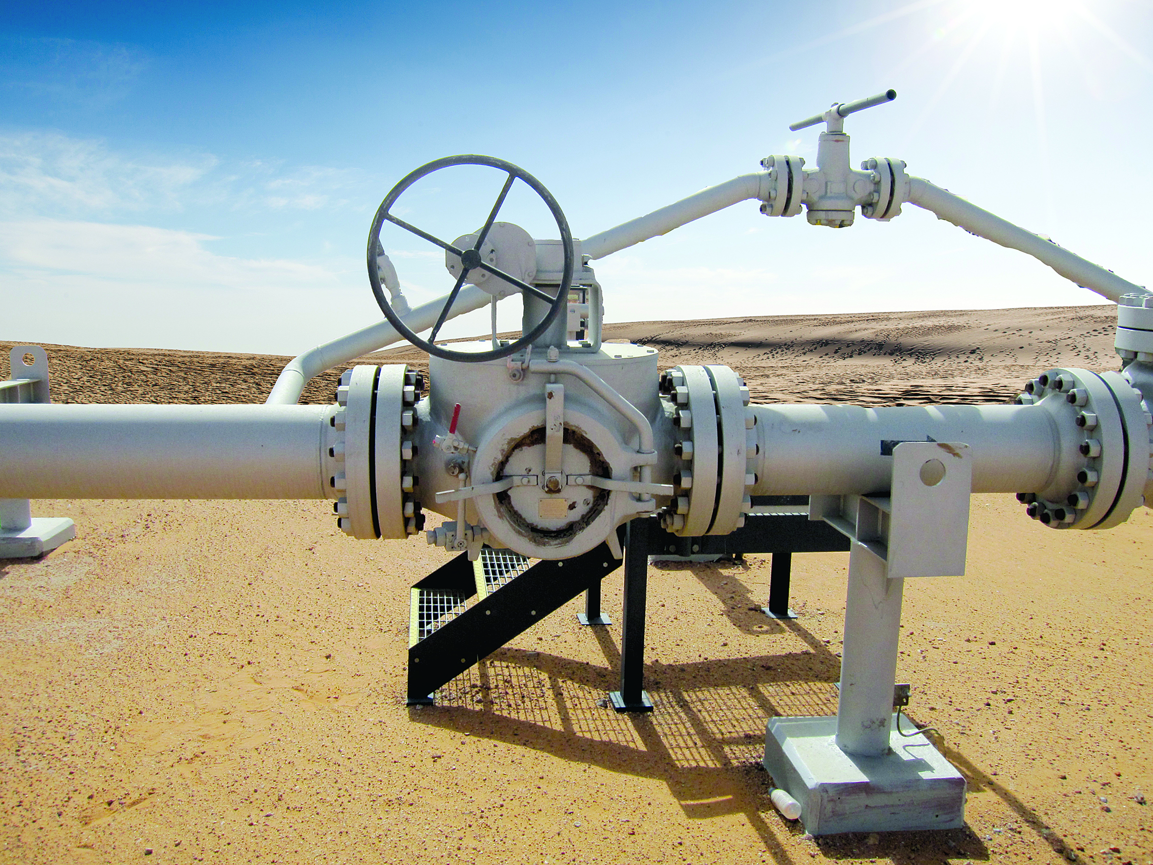
[inline:Figure3_Low_Pressure_Negotiability.jpg]
Figure 3: Low pressure or low flow can be major challenges for a successful ILI inspection.
[inline:Figure4__EcoPetrol.png]
Figure 4: Schematic drawing of a typical offshore/onshore loading line.
[inline:Figure5_Helix.jpg]
Figure 5:. RoHelix, self-propelled robotic crawler.
[inline:Figure6_Decision Chart_magazin_hochformat.jpg]
Figure 6: Flow chart for initial identification for a challenging inspection scenario.

Comments