
June 2015, Vol. 242, No. 6
Features
Engineering Mounded, Vertical, Cylindrical, Welded, Carbon Steel Tanks
Kerosene-type jet fuels are sometimes required to be stored in bulk in tanks with earthen backfill. No single code or standard addresses the requirements for construction of such tanks, which needs a multidisciplinary approach. This article provides a concise basis for aviation fuel storage in mounded, vertical, cylindrical, welded, carbon steel storage tanks.
Storage tanks are designed to withstand a variety of operational loads and environmental conditions over decades of safe and economic usage. Jet fuel storage facilities must be engineered to a set of procedures, practices and standards to provide complete assurance both of quality of product and safety of the operation.
Some facilities require the tanks to be by backfilled with earth so that their presence is not easily perceived. Such tanks are generally lesser than 33 meters in diameter and limited to 6 meters in height.
Table 1 lists relevant fuel properties that have a bearing on the storage tank’s engineering aspects. This is followed by the basic design in accordance to API 650, which is then improved upon by structurally modeling the tank using the finite element method. Special requirements for jet fuel storage are also addressed.
Jet Fuel Product Properties
Aviation fuels fall into two basic groups: aviation turbine fuels (jet fuels) for use in turbofan, turbo-jet and turbo-prop engines, and aviation gasoline for use in reciprocating or piston engines. We address storage of kerosene-type aviation turbine fuels.
Kerosene-type jet fuels have a minimum flash point of 38o C and must be treated as flammable or combustible liquids based on ambient temperature.
Basic design to API STD 650
API standard 650 establishes minimum requirements for material, design, fabrication, erection and inspection for vertical, cylindrical, above ground, welded storage tanks in various sizes and capacities for internal pressures approximating atmospheric pressure.
However, API 650 does not account for external pressure conditions due to earth backfill such as in mounded tanks. Therefore, API 650 is only used for a basic design as an input for structurally modeling the tank using FEM software.
The external surfaces of the tank are generally protected by cathodic protection and the internal surfaces by jet fuel compatible coating. A nominal corrosion allowance of 1.5 mm is, therefore, considered for the tank.
API 650 specifies minimum allowable shell plate thickness for various tank diameters. As an example, for diameters less than 15 meters, the nominal thickness of the lowest shell course shall not be less than 6 mm. Also provided are the shell design formulae in accordance to the 1-foot method for product design stress and hydrostatic test stress. The required minimum thickness of shell plates is the greater of the values computed by the 1-foot method and those listed as minimum allowable shell plate thickness.
The criteria, which determines the thickness of segmental annular floor plates, is based on stress values in the bottom course of shell plating. However, API 650 accounts for the greater of product or hydrostatic test stress only. Therefore, to account for stress from external backfill, a 10-mm annular plate is usually selected.
API 650 requires all bottom plates have a corroded thickness of not less than 6 mm. Therefore, with a corrosion allowance of 1.5 mm, 8-mm bottom plates are usually selected.
A water draw-off sump in accordance to the dimensions provided in API 650 for 4-inch water draw-off pipe is located centrally to collect water that separates and settles from stored fuel.
In case of tank empty condition, the external earth pressure of backfill all around acts on the shell, which needs to be resisted by stiffening of shell plate at required intervals along the height of the tank. The shell stiffeners are analyzed and designed by FEM 3-D modeling and structural analysis using standard software and also compared with manual calculation using Steel Plate Engineering Data Volume I & II.
Structural Design, FEM 3-D Modeling
As earth fill needs to be placed on top of the steel roof of the tank and also taking into account construction loads, we need to consider equally spaced steel internal columns with radial girders to support the roof structure.
The entire steel tank along with column-supported steel roof structure and external backfill is analyzed and designed using finite element method by 3-D modeling and analysis by industry standard software, such as STAAD Pro (or) RISA 3-D. Beam elements for girders, secondary members, shell stiffeners and plate elements for steel plates are assigned in FEM Model. Relevant codes, such as API 650, EN BS 1993/AISC LRFD govern such designs.
Wind load before external backfill and seismic loads after backfill are considered along with other forces.
The following critical load conditions are examined and tested for strength and stability of tank structure:
1. Tank under hydro-test without any external backfill.
2. Tank empty condition with external backfill.
3. Tank full condition with external backfill.
The reactions from FEM 3-D Model steel tank are then seamlessly transferred to foundation FEM 3-D model with central sump in software, such as STAAD Foundation or RISA Foundation and designed as per BS EN 1992 / ACI 318.
The critical load conditions are examined in the foundation design and checked against bearing pressure.
Jet Fuel Storage Requirements
The number and size of tanks should be sufficient to provide adequate working capacity, taking into account peak period requirements, supply replenishment arrangements and emergency stock coverage. Allowance should also be made for settling, testing and tank-cleaning requirements.
Thermal stability is one of the most important jet fuel properties because the fuel serves as a heat exchange medium in the engine and airframe. Thermal stability of jet fuels can be degraded by the presence of soluble copper and iron or by finely divided particulate matter, such as rust. In principle, zinc and cadmium can also degrade thermal stability, although their impact is less than that of copper and iron. Consequently, no copper or cadmium alloys, cadmium plating, galvanized steel, zinc rich internal coatings or plastic materials are permitted in storage tanks.
The presence of water is not acceptable in a tank lined up for “issuing.” As water is denser than jet fuel, one of the best ways to collect this water is with a steeper sloping cone down floor (1:30 slope to center sump), with a central collecting sump from which a drain pipe can be taken.
Carbon steel tanks at airport depots are required to be internally lined with compatible, light-colored epoxy material on all surfaces, including underside of the roof. A floating suction unit for the tank’s outlet is also essential.
Requirements for Mounded Storage
Jet fuel tanks are normally free-vented with only a coarse mesh to prevent the ingress of foreign bodies. However, the presence of granular fill over the roof increases the possibility of excessive ingress of sand through the tank vents. Therefore, pressure vacuum relief valves without flame arresters are considered on the vents of mounded tanks. Due to the external backfill, the tanks are not subject to fire exposure to the same level as aboveground tanks without earth cover. However, as a good engineering practice, a 24-inch roof manhole with emergency blow-off hatch is recommended to mitigate overpressure conditions.
Internal columns are not preferred in aviation fuel tanks to reduce the risk of contamination and avoid fouling with the floating suction unit. In the case of mounded tanks, the tank roof is generally flat with marginal slope to drain rainwater and is supported by internal columns. It is best to avoid tubular columns to eliminate the need of internally coating the columns.
As the tanks are mounded, leak detection is not limited to the tank bottom. A grid of fuel leak detection cables between the concrete raft foundation and tank bottom in addition to a circumferential ring of leak detection cable near the tank’s bottom shell course is considered to provide adequate leak detection. Impressed current type cathodic protection in conjunction with a suitable external painting system is considered to protect the tank against external corrosion.
Jet fuel tanks are normally equipped with a 2-inch stainless steel water draw-off line from the center sump. However, due to integrity issues posed by 2-inch pipes in the buried portion, 4-inch water draw-off line is used with jet fuel compatible coating. Access to the tank is considered using two roof manholes. All piping from the tank shell’s bottom course is routed to a reinforced concrete access tunnel that is mechanically ventilated.
Conclusion
This article consolidates requirements from various industry codes and standards along with expertise of aviation fuel specialists, mechanical and structural engineers to provide a quick guide to bulk storage of aviation fuels in mounded, vertical, cylindrical steel tanks.
Authors: Dinesh Nair is the engineering manager at the Oil and Gas Division of Mott MacDonald in Dubai, UAE. He has more than 24 years of experience in product storage and distribution terminals, onshore and offshore tanker terminals, cross-country pipelines, aviation fuel depots and bitumen storage terminals. He can be reached at Dinesh.Nair@mottmac.com.
Anup Sera is a senior mechanical engineer at the Oil and Gas Division of Mott MacDonald in Dubai, UAE. He specializes in aviation fuel storage and transportation. He has more than 12 years of experience in storage and handling liquid petroleum products and can be reached at Anup.Sera@mottmac.com
N. Veerabadran is the lead civil and structural engineer at the Oil and Gas Division of Mott MacDonald in Dubai, UAE and can be reached at N.Veerabadran@mottmac.com

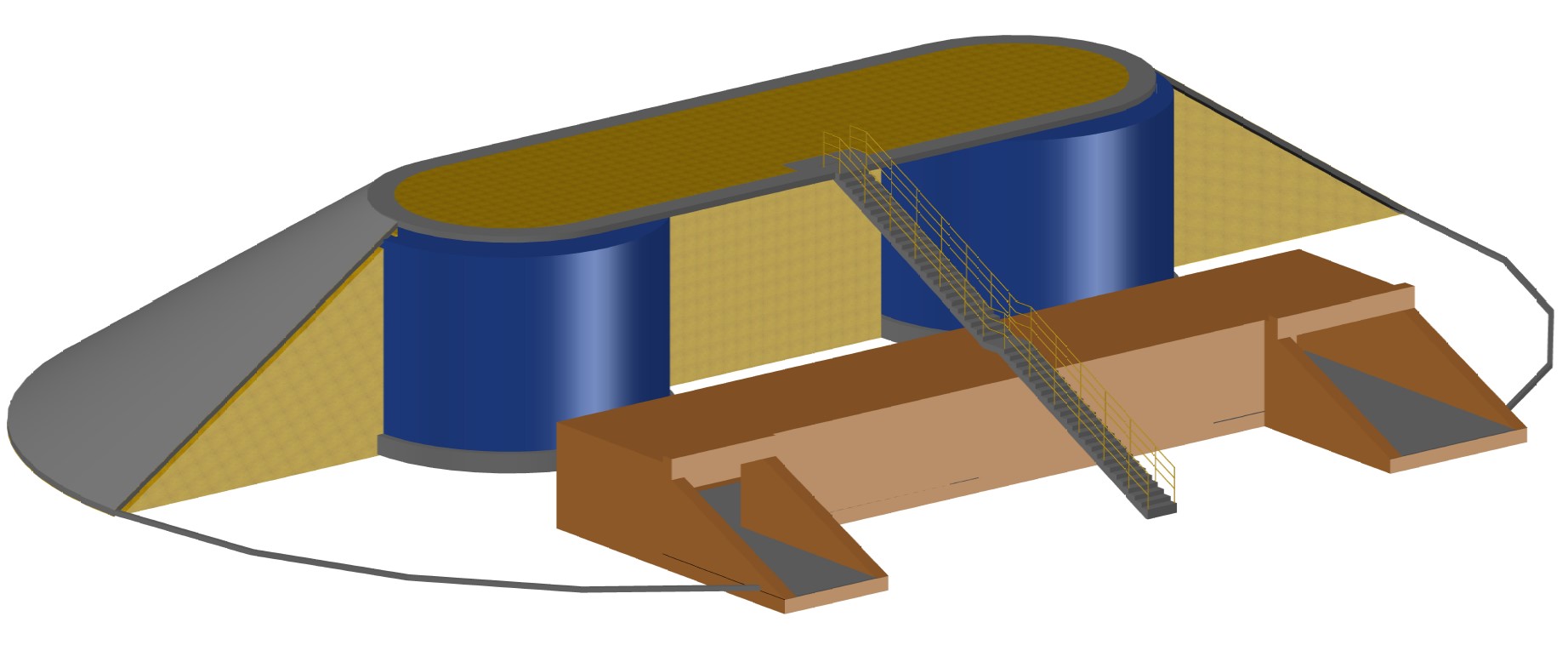
Figure 2: Sectional view of vertical, cylindrical tank with external backfill. It shows a tunnel for access to valves and piping from tank shell.

Table 1

Figure 3: FEM 3-D Model of tank.

Figure 4: FEM 3-D Model of tank raft foundation with central sump.

Comments