
April 2015, Vol. 242, No. 4
Features
Trenchless Technologies Solve Marine Crossing Challenge
Based in Queensland, Australia, the GLNG project involves gas field developments in southeast Queensland and an LNG plant on Curtis Island, near Gladstone.
Sanctioned in January 2011, GLNG includes the development of coal seam gas (CSG) resources in the Bowen and Surat Basins, construction of a 420-km underground gas transmission pipeline to Gladstone, and two LNG trains with a combined nameplate capacity of 7.8 mtpa on Curtis Island.
The project has an estimated gross capital cost of US$18.5 billion and is on track for first LNG in the second half of 2015.
The project is being developed by a joint venture made up of Santos, Total, Petronas and Kogas. The contract involving engineering, procurement and construction of the 420-km, 42-inch gas transmission pipeline and fiber optic communications running from Fairview to Curtis Island was awarded in 2011 to Saipem Australia.
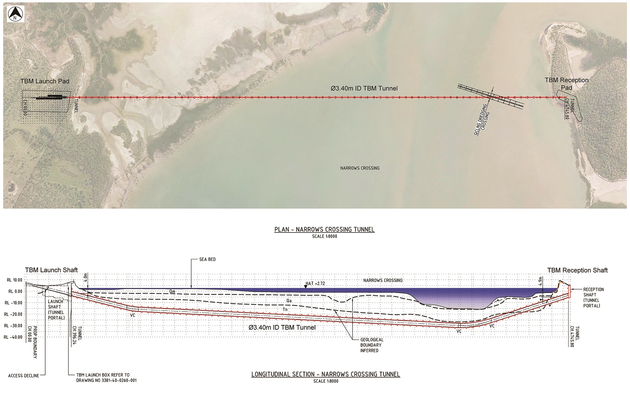
The last section of the GLNG pipeline route crosses a 4.5-km marine channel including a wide mudflat tidal plain called The Narrows before reaching Curtis Island LNG plant.
The Narrows is a sensitive marine environmental area for the near-shore native flora and fauna (Figure 1). Furthermore, the mudflat intertidal zone is also characterized by the presence of shallow acid sulfate soil layers. This particular soil, if exposed during excavation, could increase the acidity of the surrounding environment with severe consequences on the local ecosystem.
Trenchless Solution
To minimize the environmental effect of pipeline construction activities crossing this sensitive intertidal and marine area, a 4.35-km trenchless solution was preferred over traditional open-cut construction methodologies.
The final marine crossing method selected was a segmentally lined tunnel to be used as a conduit for the installation of the GLNG Gas Transmission Pipeline (Figure 2).
The Saipem project team developed a pipeline installation method by pushing the 42-inch concrete coated pipeline (API 5L X70, thickness 23.5mm) into the tunnel using a pipe thruster machine (PTM) located on the mainland.
The pipeline was installed inside the tunnel that was previously partially flooded with seawater. Flooding of tunnel facilitated pipeline installation by a significant reduction of the pipe self-weight and consequently of the friction loads acting on the concrete lining invert. The pipeline was concrete weight coated (CWC) to avoid buoyancy in the operating condition.
Once the pipeline installation was complete, the tunnel was sealed with end plugs and entirely filled with seawater to ensure it remained inaccessible over the 42-year design service life of the project.
The Narrows marine crossing tunnel alignment was 4,350 meters long, with a minimum coverage of 12.5 meters. The excavation was performed using a continuous, segmental lining earth pressure balance tunnel boring machine (TBM), with an internal diameter of 3,400 mm and a cutter-head diameter of 4,060 mm (Figure 3).
A 360-meter-long and 8-meter-wide launch shaft with a decline ramp (2.5% inclination) was constructed on the mainland in order to assemble and launch the TBM and finally to install the pipeline. Shaft walls were supported by anchored/propped sheet piles (Figure 4).
A receiver shaft (15 by 8 meters) was built on Curtis Island to allow for TBM recovery and pipeline connection tie-ins to the route section on the island.
The TBM was assembled and launched at the end of April 2013, while the breakthrough was in early February 2014. The actual excavation rate was about 16-18 meters a day, with a volume of about 55,000m3 of total excavated spoil.
Tunneling operations were performed by a 75 member team, working more than 420,000 man-hours.
A dedicated railway was constructed in the tunnel to transport spoil, concrete segments, material and personnel to and from the TBM.
The TBM was equipped with a guidance system based on a laser theodolite mounted on the tunnel lining. The TBM advancement and the tunnel alignment were checked in real time with accuracy to the millimeter. The actual misalignment at the arrival target was less than 15 mm.
The tunnel alignment was designed to minimize the construction risks with reference to the complex geological conditions expected, such as mixed soil conditions with sandy clay, gravel and mudstone.
A critical section was anticipated in the second half of the tunnel alignment where regional faults were encountered, resulting in abnormal conditions into the TBM excavation chamber: excessive high-pressure water inflows, unstable tunnel face within thick gravel layers, etc. The flexible capabilities of the adopted EPB-TBM and the dedicated tunneling procedures allowed good boring performances even in the challenging, complex and unstable soil conditions encountered.
Once completed the boring activities, tunnel commissioning and preliminary preparatory works for the pipeline installation were performed in about six weeks.
Tunnel Installation
The first step was the TBM disassembly and removal from the receiver shaft on Curtis Island. Afterward, several activities were performed to prepare the tunnel for pipeline installation, including preparation of an as-built survey, removal of the temporary services, dismantling of the railway, installation of FOC, cleaning and smoothing of the tunnel invert, and flooding of the tunnel with seawater.
Finally, the launch shaft was re-arranged for the pipeline installation activities, such as pipe rollerway setup, PTM settling and power pack/control cabin allocation, and pipe braking system installation. The pipeline installation inside the tunnel was performed using the hydraulic (PTM equipment (Herrenknecht Model HK750), installed in proximity of the tunnel portal. The PTM was to clamp the 42-inch CWC pipeline and apply a push/pull force up to 750 tons. The installation advancement rate was about 5 meter/7minutes for every thrusting cycle (Figure 5).
In addition, between the tunnel portal and the PTM, a braking system made up of a clamp mounted on a steel supporting frame was installed to avoid uncontrolled movements of the pipeline string when the thruster clamp was in open mode. The PTM and the braking system clamps were automatically activated and coordinated through a hydraulic circuit controlled by an operator in a control cabin.
The major advantages of using a PTM over traditional installation equipment (winch/linear winch), are:
• Safe installation: The risk of uncontrolled pipe string movements during installation is minimized. The PTM clamp and braking system clamp allow for a better and continuous control of the pipeline string. No objects under tension required.
• Contingency measures: PTM could possibly be used even to pull back the pipeline string already installed in the tunnel in case critical problems arise.
• Pipeline stress reduction: Pipeline rotation is minimized during installation.
• Minimization of construction risks: The risk of pipeline derailment out of the rollerway is significantly reduced due to the clamping action of the pipe thruster/brake system.
• Schedule optimization: The overall complexity of the installation system is minimized All installation activities were performed on the mainland minimizing logistical and construction related issues on the island.
The abrasion and the frictional interaction between the 42-inch CWC pipeline and the concrete segmentally lined tunnel invert was minimized by installing high-performance polyurethane collars around the pipeline, (Figure 6). This solution was specially designed and manufactured by the Saipem project team.
Intensive laboratory and full-scale testing on the polyurethane collars were performed in order to assess the mechanical performances of the proposed elastomer mixture. The selected prepolymer showed excellent mechanical properties with high resilience to stress concentration and abrasion resistance. During tunneling, to optimize the pipeline installation schedule, the 42-inch CWC single pipes were welded in the launch pad yard into triple joint pipe strings, each about 37 meters long and weighing 47 tons.
The pipeline string feeding the PTM was laid on the rollerway located along the launch shaft decline ramp and aligned with the tunnel centerline. The rollerway length was about the same as the launch shaft decline ramp, 300 meters. The adopted pipeline installation sequence along the launch shaft was conceptually similar to a pipeline firing line of an offshore pipelay vessel.
Along the rollerway, in the shallower section of the launch shaft, different working stations were accommodated along every triple joint length of pipe: three PASSO semi-automatic welding stations, one NDT station, one field joint coating station and one joint infill station.
The pipeline installation was performed by a cyclic two-phase work sequence:
Phase 1: Triple joint pipe strings installed on the rollerway – Three 42-inch CWC-triple joint pipe strings were laid in sequence on the rollerway using a 250 ton crane positioned on top of the launch shaft (each CWC weighed about 1.3 ton/meter.
The semi-automatic welding stations located in the shaft sequentially proceeded fitting and joining the triple joints to the 42-inch CWC pipeline string already laid on the rollerway. In the same time frame, the other working stations were performing the other activities on the pipe joints in running order, such as NDT and field joint coating.
Phase 2: Pipeline entering tunnel – The PTM started to push the 42-inch CWC pipeline string into the flooded tunnel for a length equal to three triple joints.
Each phase required about 90 minutes to complete.
The work sequence restarted cyclically; when Phase 1 was completed, Phase 2 activities began. The installation production rate of a single working cycle was 115 meters/3 hours.
Critical engineering aspects of the proposed pipeline installation method have been duly addressed during the detail design phase. The following required finite element modeling: pipeline potential buckling during installation, pipeline stress analysis during installation and operational phase, interaction CWC pipeline/tunnel lining, interaction CWC pipeline/rollerway and evaluation of installation loads.
Dedicated full-scale tests have been performed to check interaction CWC pipe/PTM clamps, anti-abrasion collars performances, CWC cutback infill with rapid set concrete and interaction CWC pipeline/rollerway.
Installation of the 42-inch pipeline into the 4,350 meter-long tunnel was successfully performed in 15 days, with crew working 24-hour shifts (Figure 9).
Dedicated H&S risk workshops (Design HAZID, Construction HAZID, Safety in Design) were held jointly. As a result of the health and safety approach adopted, the pipeline installation involving about 150 workers for a total of about 150,000 man-hours, did not record a single lost time incident or near miss event.
Completion of the Narrows Marine Crossing was achieved in June and included pipeline pre-commissioning, sealing of the tunnel with concrete end plugs, installation of CP system, pipeline installation within transition zones at both ends of the tunnel, tie-ins, backfilling and final reinstatement (Figure 10).
The pipeline installation works were carried out in compliance with Australian and international standards. All the activities were certified by a strict QA/QC inspection project test plan.
The GTP installation has been completed in line with design expectations. In particular, no significant unforeseen event has been recorded, and all the design parameters monitored during installation were in line with the engineering models developed. The maximum actual resisting force measured at the PTM was 270 ton vs. an expected value of 350 ton. The results are ultimately coherent with the factor of safety assumed.
A dedicated full-scale validation test has been carried out in the PTM’s manufacturer’s factory. Moreover, in accordance with the case history investigated, the GTP installation is the longest to date ever performed using a Pipe Thruster Machine – 4,350 meters.
In the light of the result achieved, the adopted installation concept might be further developed for more demanding scenarios, such as bigger pipeline diameters and longer tunnel lengths.

Figure 2

Figure 3

Figure 4

Figure 5

Figure 6

Comments