
October 2014, Vol. 241, No. 10
Features
Inspecting And Protecting Buried Piping In Presence Of Electrical Grounding
Many pipeline facilities including compressor stations, regulator stations and pump stations/tank farm terminals have thousands of feet of buried pipe that are not readily accessible for direct inspection. The presence of buried electrical grounding systems that may incorporate copper cables and rods or galvanized grounding elements pose challenges to achieving adequate corrosion control and the assessment of buried piping.
As a result, the traditional indirect, over-the-line inspection practices developed for the oil and gas transmission and distribution pipelines have not always been successfully applied for station/plant environments.
To address these challenges a collaborative research project was established with Mears Group, Inc. In this program, initial testing of four methods was carried out at the Mears Research and Development Test Facility in Rosebush, MI. This was followed by testing of the same methods at operating facilities. This article discusses the results of the studies and presents some of the findings that can help to overcome the challenges faced when grounding and dissimilar metals are in direct contact with piping to be assessed.
The design, construction, and operation of compressor/pump stations and tank farm terminals represent a major capital expenditure. Downtime and replacement costs for corroded equipment and materials can result in exorbitant operating and maintenance costs, not to mention the loss of revenue and cost of clean-up in the event of a release of hydrocarbon product. Corrosion and material degradation of buried piping in a plant resulting in leaks and failures is a significant issue, not only due to operational and safety concerns, but also because of regulatory requirements for protecting the environment and public health.
The primary structures of concern when considering underground structures are pipelines which are direct buried, direct-buried storage tanks, ground storage tank bottom undersides, electrical grounding grid and cast or ductile iron fire protection and potable water piping. Many of these structures are commonly exposed to a corrosive environment and galvanic corrosion can be expected.
Most station/plant ground grid systems are designed to provide an extremely low resistance to remote earth in order to facilitate personnel and equipment safety under fault conditions or lightning events. As such, an electrical design engineer will require that all structures within the station/plant be effectively tied into the grounding system. This is a common industry practice and cannot be effectively altered, nor is it desirable to do so. This practice, while enhancing safety, can also result in the rapid deterioration of piping systems in the absence of suitable corrosion-control procedures.
The most successful means of establishing corrosion control for underground structures is the effective combination of a protective coating in conjunction with the application of cathodic protection. Assessing the coating condition and location of flaws (if any) and potentially injurious corrosion can greatly enhance integrity management efforts.
Indirect inspections (often referred to as over-the-line surveys) gather information on coating and CP condition and provide an integral input to any risk ranking of piping inspections. The indirect inspection techniques have proven to be very successful in the oil and gas transmission and distribution integrity management efforts, enhancing quality of data obtained by direct inspections, enhancing safety, and contributing to overall cost saving and quality assurance of the integrity management programs.
Unfortunately, experience with indirect inspection methods in compressor/pump station and tank farm terminal facilities is still very limited, and traditional indirect inspection techniques face challenges.
In 2011, a collaborative project involving Mears Group, Inc. was established to perform field assessment of various techniques. The first phase was intended to evaluate the selected indirect inspection methods in a known situation simulating the plant conditions (such as grounding) and was performed at the Mears Testing Facility.
The objective was to evaluate selected indirect investigation techniques that are widely used in the oil and gas industry as feasibility and limitations for use on piping systems that are (1) grounded, (2) installed in a complex network, and (3) close to station buildings and components.
Four indirect inspection techniques were used during the test program, including Pipeline Current Mapper (PCM), Alternating Current Voltage Gradient (ACVG), Direct Current Voltage Gradient (DCVG), and Close Interval Survey (CIS). A brief description of these over-the-line survey techniques follows.
Pipeline Current Mapper
Pipeline Current Mapper (PCM) is used to locate the pipe, identify areas of current loss, and the depth of cover of the buried pipe. A PCM attenuation curve along the buried piping could also be used to indicate the difference in coating resistance and the location of potential coating damage.
The PCM survey uses a low frequency 4 hertz (Hz) signal current to measure current attenuation characteristics as well as to locate pipeline electrical contact (shorts) to other buried metallic structures. A secondary 8 Hz signal provides current direction information when the PCM is used in the ACVG mode. The signal current is applied on the pipe by connecting a transmitter to the pipeline at a rectifier where there is low resistance to ground of the CP anode bed.
Pipeline sections with no CP can be connected to a transmitter that is grounded to any remote or semi-remote earthed metallic structure as long as it is not bonded to the AC ground grid or the pipeline. The attenuation of the current is measured and plotted over the length of the pipe after the pipeline is located and the depth of cover is recorded.
Alternating Current Voltage Gradient
Alternating Current Voltage Gradient (ACVG) is similar to DCVG with the exception that the applied current is an alternating signal. ACVG surveys use the same transmitter and receiver as the PCM survey method with the addition of a pair of probes assembled at a fixed distance. The intent of the ACVG survey is to identify coating anomalies and measure the size. The equipment uses a low frequency 4 Hz signal current of sufficient strength to be measured at the ground surface above the pipeline.
The surveyor walks over the pipeline in a direction away from the signal connection location at three-to-four-foot intervals. The surveyor places the pins firmly in the ground and notes the signal direction and strength. When a reversal in signal direction occurs, the surveyor retraces with intervals at closer spacing until the highest voltage in µV is observed. This indicates the location of coating flaws. The surveyor then changes the probe orientation and records the signal strength perpendicular to the pipeline, which is an indication of the coating flaw size.
Direct Current Voltage Gradient
Direct Current Voltage Gradient (DCVG) uses the signal information of the lateral and longitudinal surface voltage gradients of an externally applied DC current on the pipe to locate coating flaws. The theoretical voltage gradient at a single coating flaw (valid for both DCVG and ACVG) could be described by the radial equal potential gradient lines in an ideal situation (with uniform soil resistivity). Generally, with current concentrating on a single coating flaw, it flows through the soil, producing a voltage drop that is proportional to the soil resistivity and distance.
The DC current can be applied through the existing CP system anode ground bed (if remote from the pipeline) and rectifier, or with a temporary CP system. The current is interrupted (by turning on and off) in a continuous cycle that results in an oscillating gradient field. Specialized equipment is used to measure the magnitude of the voltage gradient cycle with probes contacting the ground surface.
The surveyor walks directly over the pipeline in the direction away from the location of the signal connection using soil contact probes in a manner similar to walking sticks. The surveyor places the pins firmly in the ground at approximately five-foot spacing and notes the swing signal strength and direction. As a coating flaw is approached, the swing signal amplitude will increase and then reverse direction after the coating flaw is crossed.
When a reversal in signal direction is noticed, the surveyor retraces until the signal is null. The center of the pin span is the location of the indicated coating flaw. The surveyor then changes the direction of the pin span, and the side drain measurement (perpendicular to the pipeline) is then performed on both sides of the pipeline. The side potential gradient readings are used to calculate the relative size of the indicated coating flaw along with the signal attenuation from the connection point.
Close Interval Survey
Close Interval Survey (CIS, also referred to as CIPS – Close Interval Potential Survey) measures the pipe-to-soil potential at equally spaced intervals directly over the buried pipeline section.
For transmission pipelines, the CIS is primarily used to assess the effectiveness of cathodic protection and identify large areas of coating deterioration; it is not very useful in identifying or locating small coating flaws.
The surveyor walks directly over the pipeline, stopping at evenly spaced intervals. The reference cell is placed firmly on the ground at each interval for a stable reading. During an interrupted survey, both CP current “on” and “off” measurements are recorded. During a native (free corrosion) potential survey, a single reading is stored at each interval. The interval spacing should be no more than twice the depth of the pipe but may need to be closer in congested areas.
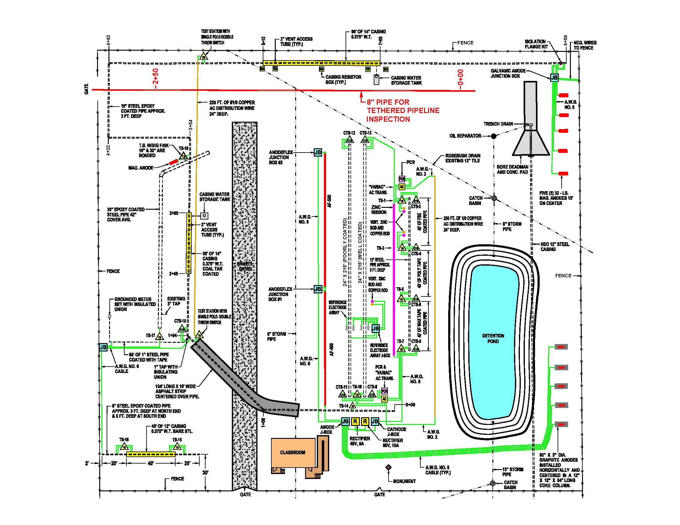
Mears Research And Development Test Facility
The piping system inspected was a 10-inch OD carbon steel pipe, buried in mildly corrosive (6,000-10,000 ? cm) soil, with a two-part liquid epoxy protective coating system on the exterior of the pipe. The pipe section inspected has CP applied by an impressed current system using parallel linear anodes. The total length of this pipe section was 852 feet.
The pipe is buried approximately four feet below grade elevation. The general route of the pipeline traverses under asphalt paving, gravel, and soil. The pipeline also passes through two steel cased crossings. There were a number of known coating flaws that have been intentionally created in the external coating of this pipe section with the following sizes: 1 cm2, 5 cm2, 10 cm2, 20 cm2, and 40 cm2.
The tests were performed in five configurations:
- Baseline condition with the 10-inch pipeline electrically isolated from all grounding elements.
- Pipeline connected to a semi-remote 200-foot bare #1/0 AWG copper ground cable with a #12 AWG insulated copper wire at a test station just downstream of the first casing.
- Pipeline connected to three vertical semi-remote copper ground rods with a #12 AWG insulated copper wire at the test station just downstream of the first casing.
- Pipeline connected to a close (three feet apart) parallel 275-foot bare #1/0 AWG copper ground cable with a short #8 AWG insulated copper wire at a test station that is located Pipeline connected to all above-mentioned groundings including both copper ground cables and copper ground rods.
A linear anode was used as the current source for CIS and DCVG testing and the five vertical anodes in the southwest corner of the facility were used as the current source for the signal in the PCM and ACVG testing.
Table 1 is a summary or the ACVG and DCVG indication data by approximate location against those found in the baseline-isolated survey. The observed signal strength of each indication is included. The red-shaded locations are large flaws that were only detected by one test method and with poor stationing correlation. The green-shaded locations are where the indications and actual locations correlated well. In general, the ACVG located more coating flaws than DCVG when the semi-remote cable and ground rods were connected. Both techniques did poorly when the close ground cable was connected.

As expected, the CP current required for adequate protection and the signal required for detectable voltage gradients at coating flaws increased as the amount of grounding connected to the pipeline increased. The baseline-applied CP current was 7.5 mA and the DCVG-applied current was 10 mA. With the semi-remote cable added (Test 2) the CP current was 405 mA and the DCVG current was 435 mA. This indicated that 98% (CP output) of the applied current was collecting on the added grounding in Test 2 (semi-remote cable).
In Test 3, with the ground rods connected, the CP current was 35 mA and the DCVG current was 160 mA. This indicated that 79% (CP output) of the applied current was collecting on the ground rods in Test 3. With the close bare ground cable (Test 4) the CP current was 385 mA and the DCVG current was 480 mA, indicating 98% of the current was collecting on the ground cable in close proximity to the buried pipe.
In the combined configuration with both cables and the ground rods connected (Test 5), the applied CP current was 555 mA and the DCVG current was 580 mA. This indicated that 98.6% of the current was collecting on the grounding elements in Test 5. It is likely that the same relative current splits occurred during the ACVG surveys.
With the overwhelming majority of the applied and signal current going to the grounding elements, the expected voltage gradients at the pipeline coating flaws are much smaller than those around the grounds. This was most significant where a connected ground was close and parallel to the pipeline (Tests 4 and 5).
The coating flaw DCVG lateral gradients were masked by the larger cable gradient and there were false directional (axial) gradients along the pipeline. The ACVG and PCM surveys were also affected by the parallel cable in close proximity to the buried pipe by what appeared to be a self-canceling of the signal along the parallel cable.
With the semi-remote cable connected during the DCVG measurements, the lateral gradient (relative flaw size indication) was disrupted by the cable gradient in the direction of the cable. In DCVG the gradients past the ground element connection point became particularly weak and difficult to locate and quantify.
In this demonstration the grounding elements were all near or between the DCVG or PCM current source. This increased the amount of signal current collected on the connected grounding elements versus the pipeline. Moving the signal current source to the opposite side of the pipeline and/or changing the connection location would have improved the sensitivity and the results.
Conclusions
The indirect assessment methods evaluated in this study can be used to locate coating flaws on buried piping in compressor/pump station and tank farm terminal environments. The congestion and electrical connection to grounding elements commonly found at these facilities affects the performance of these methods.
The loss of test signal current to the electrically connected foreign structures is the primary challenge as it reduces the strength of the indication observed by the surveyor. To some extent an experienced and careful surveyor can overcome this. When the site has very high resistivity soil, the limited signal current is all lost to the foreign structure (grounding and foundation elements) and there will be no observable indications on the pipeline.
Using the PCM to locate the pipeline (as is typically done during oil and gas transmission line surveys) may not be applicable to plant-buried piping when connected to grounding elements. In a plant-buried piping survey the pipeline should be located and marked prior to the coating flaw survey. This could be done by careful review of available drawings, direct or induced signal radio frequency pipe locators or ground-penetrating radar. Although the induced current output is limited to one watt by federal regulations, higher output direct-connected units could be developed.
Both the ACVG and DCVG methods are affected by the connection to grounding elements, particularly when the pipeline is grounded at both ends. The loss of signal strength makes the coating flaws very difficult to detect, particularly at sites with high soil resistivity (> 50,000 Ohm-cm) that limits the applied signal current. With the DCVG method, additional signal current can be applied with higher output (up to 80 VDC) temporary rectifiers. The existing equipment current output capacity limits the ACVG method. In both cases, temporary anodes or ground rods can be used to lower the circuit resistance for the applied signal.
Close-spaced CIS (2½ foot internals) can identify coating flaws when the pipeline is polarized by applied CP current. In very high resistance soil, the potential difference between a native coating flaw and the mixed potential of the pipe near the grounded end is small and not obvious. This method has the highest coating flaw indication resolution on cathodically protected and electrically isolated pipe sections.
As expected, the performance of all the indirect assessment methods tested is significantly improved by electrical isolation of the pipeline from grounding and foundation elements. Signal injection from multiple locations and from the ends of pipeline segments assessed is necessary to help overcome the inherent challenges of utilizing these assessment techniques in complex piping environments with local grounding present.

Comments