
July 2014, Vol. 241, No. 7
Features
Optical Strain Measurement For Subsea Pipeline Testing
Ensuring the integrity of subsea pipeline welds is vital for the oil and gas industry, with potentially damaging practical and economic consequences resulting otherwise. Vigorous testing before the pipe is placed to service is crucial and can be the difference between a successful project and an expensive disaster.
However, such testing comes with challenges. Modern techniques used in the installation of subsea pipelines can impose relatively high levels of plastic strain in the pipes being laid. Therefore, to assess the properties of pipes and associated girth welds after installation, it is necessary to simulate the straining process in a laboratory environment.
Traditional methods of simulating plastic strains generated during installation have used bonded strain gauges. However, work has been carried out at Exova’s specialist mechanical and fatigue testing plant in Daventry, UK, to measure the limitations of this type of gauge. Most notably, the gauges may vary in performance when subjected to multiple reversed plastic strain cycles, which is not surprising, given that bonded strain gauges are essentially elastic devices. Consequently, the team researched improved methods of measuring applied strains and carried out performance comparison tests on two optical strain measurement (OSM) systems.
The results showed that the alternative systems offered more accurate and reliable performance with reduced consumable costs and specimen preparation times. These findings could have a lasting effect on the way subsea pipelines are tested in the future.
An increasingly significant number of offshore installation vessels employ pipe reeling systems, making them an industry-wide trend. This method employs a string of pipes welded together onshore and wound onto the vessel around a large-diameter storage reel for transportation. Installation involves the pipe string being “overboarded,” a technique that sees the string wound out of the storage reel over a similarly large-diameter aligner reel and then into a clamping mechanism that straightens the pipe before it enters the water.
While efficient, this method is demanding upon the pipeline and its welds as the reeling cycle process imposes high levels of plastic strain in the pipe and weld material. For any post-installation assessment of fracture toughness and material properties, the imposed strain of the installation must be taken into account.
One way of achieving this has been to simulate the reeling cycle of the whole pipe in the laboratory before test specimens are extracted from the sample pipe material. This is expensive and limits the number of samples that can be extracted. An alternative is to remove relatively small strip samples from across the weld and impose the strain on individual sections of material loaded to a set of target strain values. These are usually calculated using reeling parameters such as reel radius, pipe diameter and pipe wall thickness.
Industry standards must be adhered to during this process; for example, DNV-OS-F101, requiring the strain to be measured either side of the weld and on the inner and outer wall of the sample.
Since 2010, the Daventry facility has assessed alternative methods of measuring strain that aim at mitigating some of the limitations found in strain gauges. Particular focus has been placed on two optical variants: laser light source and high-resolution cameras.
Through testing and experimentation, it has been found that OSM systems offer several benefits. Crucially, they are not susceptible to mechanical degradation during testing, so accuracy can be maintained, regardless of the loading and cycle length of testing.
Being almost completely non-contact, they are also extremely flexible with virtually no limitations on the types of rigid materials that can be tested, allowing for greater scope in analysis and practicality.
Timing and costs are important factors in testing. Both systems offer quicker test coupon preparation when compared to bonded strain gauges, requiring only removal of surface mill scale, spraying with low-reflection paint and installation of contrasting adhesive-backed markers where gauges would usually be located.
Laser System
The first system tested was laser-based. The apparatus used a pair of laser-light source generators, one aimed at the outer “cap” surface of the test coupon, the other aimed at the inner “root” surface, to scan the sample.
As the light source passes from a black-painted surface over a white marker, the reflected light is diffused. Changes in diffusion are tracked and software interprets each scan of the light source, which is then compared with the previous image and changes in elongation or compression between them calculated. The resulting data is converted into a real-time strain output for real-time analysis.
Trials undertaken compared the results of dummy test coupons, instrumented with both strain gauges against laser-system markers and calibrated extensometers. Post-verification work proved that the laser system measures strain to within, at most, 0.05% to a magnitude of 3% strain. While these figures were considered accurate, some challenges were identified during the trials. Some variation in precision, due to changes in ambient light conditions and local temperature fluctuations, was noted, and precautions had to be taken for future testing to avoid these influences.
Following the investigation, trial and verification process, finalized system specifications were provided to the manufacturer by the team and, after a final shakedown, the complete system was installed in the Exova Spijkenisse, Netherlands laboratory and has been in use in the Netherlands since 2012.
Real-Time Strain Sensor System
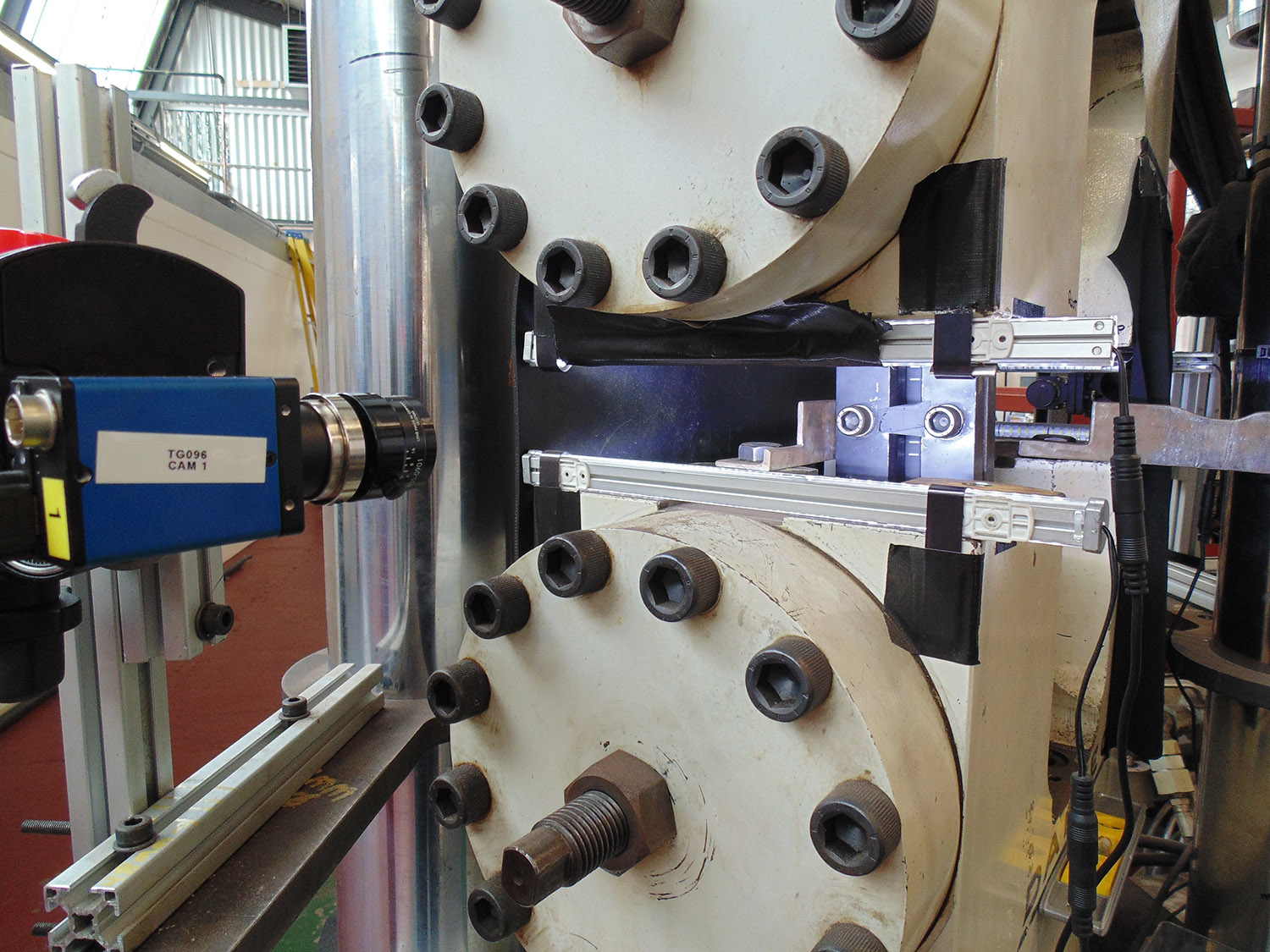
The second system examined was a camera-based module. Named “Real-Time Strain Sensor” (RTSS), it consisted of two high-resolution cameras aimed at the test coupon and operating at a frame rate of about 200 Hz. The system identifies significant contrast change to determine the position of the markers.
This is similar in principle to the marker-detection process of the laser system. The software tracks the pixel change between markers during loading by comparing the latest frame to the previous frame. This then converts the change into a real-time strain output.
A major difference between the systems is the need for much greater light in the area on which the RTSS camera is focused. The need to use an “anti-buckling device” that encases the test coupon during compressive loading shields the markers from ambient light. Therefore, an external light source is required.
A number of different light sources were tried with a series of thin, high-intensity white LED array bars mounted on the testing machine’s crosshead and bed working best. These provide enough light to enable the camera system to run with very low gain settings, with the additional benefit of flooding the sample with enough illumination to reduce the effects of external light fluctuations.
Further trials on the camera-based system showed that painting the anti-buckling device in “blackboard” paint, with extremely low levels of reflectivity, helped to reduce the likelihood of the camera system accidentally targeting a reflection instead of the markers.
In both cases, verification work has shown that OSM systems offer an accurate, cost-effective alternative to electrical resistance bonded strain gauges, especially as there is no mechanical degradation when the test material is subjected to cyclic plastic strain. For the laser system, signal quality, when compared with strain gauges, can be more open to influence from external sources, such as air flow and ambient light fluctuations. However, the implemented setup has ensured that signal quality is well within acceptable limits to provide the levels of accuracy required.
The RTSS proved to be less sensitive to the surrounding environment, is quicker and less complex to set up and can be transported between test rigs with ease. The comparative flexibility of these modules has meant that it has been possible to use them in multiple testing activities. The present RTSS camera systems have been used in a number of two- and four-post test frames, ranging from 50-1,800n kilonewtons (kN) capacity to test specimens of varying length and cross-section with cyclic strain cycles of up to 3.5%.
These alternative uses for the equipment are another driving force when it comes to considering this type of OSM system. The camera system has been used to perform cycle straining of pipe material.
Conclusion
The adoption of OSM systems has significantly reduced preparation time when compared with strain gauging. In what is usually a very time critical test process, this is important.
Looking to the future, non-contacting OSM for pre-straining has been adopted in Daventry and the Netherlands and is expected to be transferred to Singapore shortly.
This continued rollout shows how influential these new findings have been. The transition to OSM systems for this aspect of testing of subsea pipelines will continue to be a popular technique.
Authors: Dale Major is responsible for Exova’s Daventry laboratory’s fracture mechanics testing activities and resources. He has practical and supervisory experience in the testing industry for both the consumer and industrial markets. Major has managed several significant project testing programs in support of subsea pipeline ECA projects across the world.
Ed Fowkes is a technical specialist and production manager based at Exova’s Daventry facility. He is responsible for ensuring test programs meet the clients’ technical and commercial needs. Fowkes has overseen multi-stage testing projects, predominantly for the oil and gas industry.

Comments