
August 2013, Vol. 240 No. 8
Features
Using 3D Imaging To Evaluate Damaged Subsea Pipelines
Damage to subsea pipelines can cost operators millions of dollars in downtime, lost production and repairs. Common damage events such as dropped objects, anchor drag and trawler impacts can result in dents, cracks, pitting and gouges of pipeline material. Damage events compromise the integrity of pipelines and can have significant operational and financial consequences.
With pipelines and flowlines increasingly being located in deeper water and more remote locations, the stakes are higher. There is a need to quickly and accurately identify and evaluate damage to subsea pipelines so that operators have the information they need to efficiently respond to damage events.
3D Imaging Technologies
Welaptega Marine helps offshore operators evaluate damaged pipeline conditions using 3D subsea inspection technologies to produce high-quality visual inspection video footage and dimensionally accurate 3D models. Viewing and analyzing 3D pipeline data allows operators to determine the nature of damage and make critical decisions as to whether repairs are necessary.
The imaging technologies are deployed to acquire data, and to verify and remedy damage caused by offshore incidents and impacts. Notably, the 3D technology was used by BP to help visualize and resolve damage on the leaking Macondo Deepwater Horizon well in the Gulf of Mexico.
A high-definition (HD) 3D video camera system is deployed by ROV to capture HD stereoscopic video footage of pipelines and other subsea architecture. This allows operators to identify damage during real-time inspection or during playback review. The video cameras are rated to 3,000-meter water depth and are useful for general visual inspections and damage identification and investigation. The spatial awareness provided by high-definition 3D video enhances the viewer’s ability to identify deformation and material loss.
In addition to 3D Video, 3D Modelling (3DM) photogrammetry technology generates geometrically accurate 3D models of damaged subsea components such as pipelines. The technology uses advanced photogrammetric techniques to generate 3D models from 2D images of damaged components, which are captured using a pair of subsea cameras deployed by ROV.
3D models are constructed by matching pixels between overlapping images and using statistics to determine component geometry through a series of iterations. The camera system offers flexible deployment with little site preparation required. Typically, the surface is cleaned, and then one or more magnetic scaling targets are placed in arbitrary locations on the component. Camera positioning for image capture is flexible, and the ROV can free-fly if necessary.
Resulting 3D models are accurate representations of existing component or pipeline conditions and can be measured to determine the geometry of damage or anomalies such as curvature, cross-sectional areas and gouge depths, widths and heights. 3D models can be exported in formats compatible with finite element method software packages for stress/strain analysis.
If a clamp is required for pipeline repair, the 3D model can be exported to industry-standard CAD (computer-aided design) packages so that a custom design can be fitted to the damaged pipeline geometry.
A team of engineers work with operators to establish project requirements and deliverables to ensure all required measurements and analysis can be performed. Personnel travel offshore to interface subsea camera systems, set up and operate viewing equipment topside, and to ensure high-quality video and image data are collected. Following offshore operations, personnel process the collected data to produce 3D models, take measurements, and communicate with analysis providers to conduct fitness-for-purpose evaluations. Results of offshore inspection surveys, processing, measurements and analysis are provided to operators in detailed final reports.


3D Photogrammetry
In this case study, an 18-inch natural gas pipeline running along the seabed at a depth of 2,300 feet was dented and dragged 1,500 feet (460 meters) after it was hooked by an anchor.
The incident forced the operator to reduce pipeline capacity until the exact nature and extent to the damage could be ascertained and repaired if necessary. To perform in-depth analysis and evaluate the component’s condition, the operator required detailed and accurate pipeline geometry. 3D technologies were deployed at the site of damage to capture 2D images of the accessible surfaces of the 2-meter section surrounding the dent.
The 3D model was measured to determine the radius of the curvature in the pipeline. Cross-sections were taken at 4-inch increments along the length of the model. Next, a circle of best fit was aligned with the center points of the cross-sections to determine the pipeline curvature.
The 3D model geometry was exported in a format compatible with industry-standard 3D drafting and analysis programs. The curvature analysis report was also provided to the pipeline operator.
The 3D model was used to determine the structural integrity of the pipeline using finite element analysis. It was also used to construct a test pipe with the same geometry for full-scale destructive testing. After that, the model was again used to design a clamp to fit the precise pipeline geometry.
The records of analysis, non-destructive, and destructive testing were later used by the operator as evidence of due diligence in a court case.
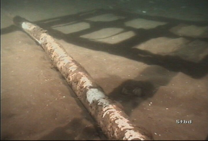
In another incident, the 3D technology was used for analysis of a 3-inch MEG (Mono Ethylene Glycol) pipeline that was believed to have been damaged by trawler activity.
The MEG line was impacted and dragged about 2 meters from its initial location. Two areas of damage were identified: a scratch in the pipe coating and a gouge or dent in the coating and the metal of the pipe. The damage spanned a length of about a meter. As a result of the damage, the pipeline operator reduced the operating capacity.
To determine how to proceed, the operator required accurate measurements of the dimensions of the deformation at the point of impact, and identification of the location where the curvature was most pronounced.
Before the data was collected, the seabed was dredged beneath the 1-meter section of the pipe that was damaged. This enabled the camera system to access the underside of the pipe.
The damaged section of the pipe was then grit-blasted to remove the white coating to expose the bare metal, so that the 3D model would represent the pipeline itself, rather than the coating.
Before the pipe was photographed, divers were instructed to mark the shiny surface with a black-and-white grid pattern. This created a contrast in the images and facilitated image processing. The images were collected along the 1-meter pipeline surface by deploying the camera system on the seven-functions of a work-class ROV. Then they were processed to generate a 3D point cloud which was meshed to produce a 3D model. The dimensions of the deformation were examined and the operator provided with measurements of width and depth.
The depth of the gouge was measured with respect to the original surface, which was estimated based on surrounding baseline data. The radius of curvature was also measured by aligning a circle of best fit with the central axis of the pipeline. This procedure was performed over interval sections of the line to determine where the radius of curvature was the smallest. Resulting measurements were used to perform an engineering assessment of the pipeline condition.
The operator determined that the pipe was in suitable condition to continue operation without repair. Using the 3D model of the damaged pipeline for stress/strain finite element analysis enabled the operator to avoid the costs and lost production associated with repair work.
In both cases, the pipeline operators were able to assess the extent of damage and make informed decisions as to how to proceed. Data collection was performed with no impact on production since only minimal site preparation and photography were required.
Author:
Marie MacCormick graduated with a degree in mechanical engineering from Dalhousie University in Halifax, Canada. She joined Welaptega Marine in 2007 to develop the company’s subsea 3D modeling capability and has executed subsea projects in Canada, Norway, the Gulf of Mexico, Australia and the United Kingdom. She can be reached at: m.maccormick@welaptega.com.

Comments