
August 2013, Vol. 240 No. 8
Features
Commercial Robotic Inspection Solution For Unpiggable Pipelines
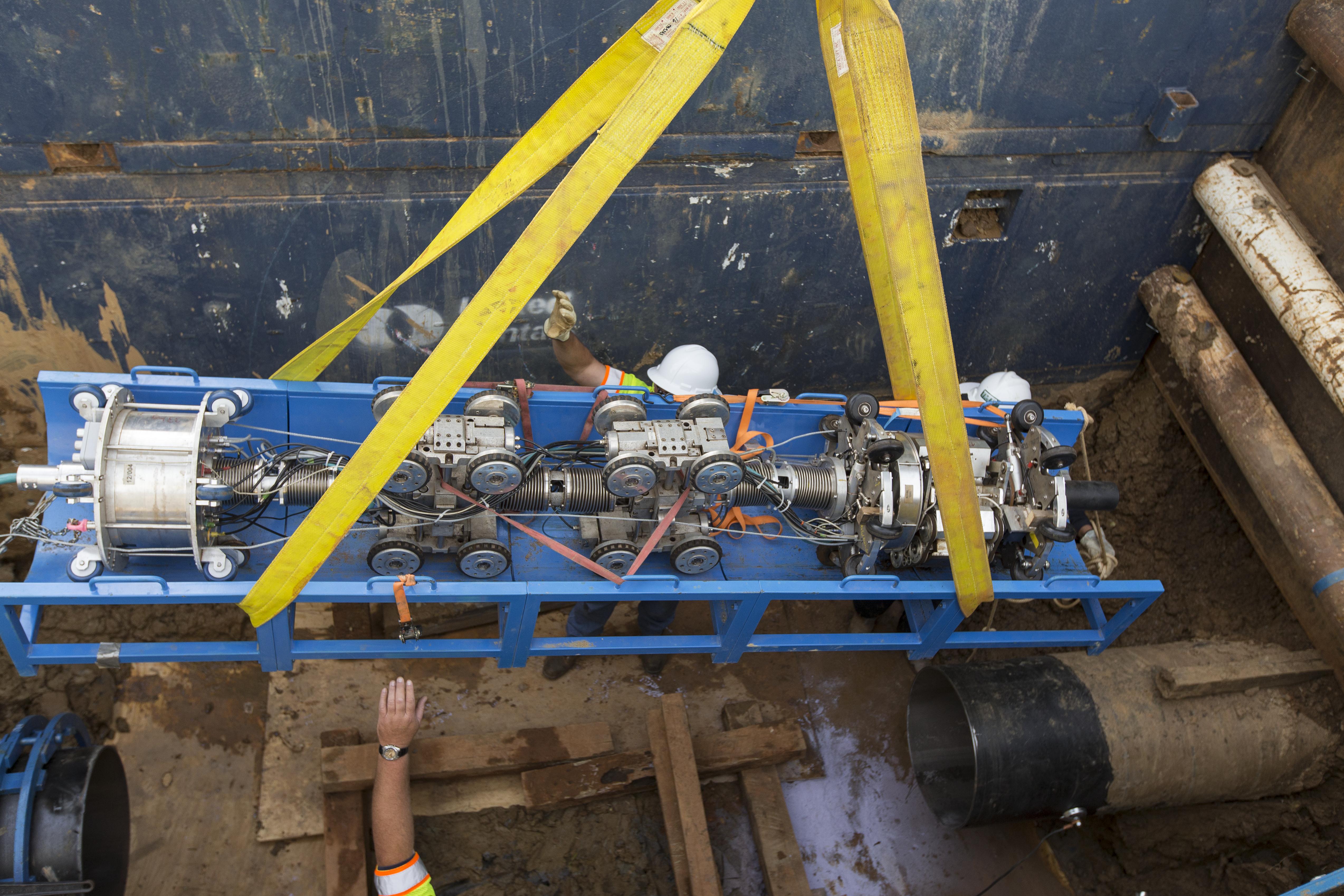
A self-propelled inline inspection tool has been commercially used to inspect oil and gas lines. Surveyor, a robotic tool provided by GE’s Industrial Solutions, has been used to inspect more than 35 cased crossings or terminal tank lines. The benefit of using this tool has been its capability to quantify metal loss both internal and external and the relative ease to insert and retrieve the tool into the pipeline, thereby foregoing pipe modifications for traditional smart pigs or time required for hydrotesting.
Surveyor can enter and exit a pipe from the same location, traverse a relatively complex piping configuration and discriminate areas of metal loss. It is suited to inspect short (less than 1,000 feet) unpiggable piping common for facilities and cased crossing. Moreover, it can inspect pipes that are empty, half full, or filled with liquid.
Facilities where the tool is to be considered include the following:
• oil and gas terminals
• refineries
• industrial sites
• connecting petrochemical lines
• feed lines for combined cycle gas plants
• cased pipeline crossings and distribution pipelines
A large benefit is the tool allows these facilities to inspect their buried lines at reduced project cost. Traditional inline inspection tools require significant pipe modifications associated with the installation of a launcher and a receiver. Furthermore, sufficient flow and pressure is required to push the passive “smart pig” tools to ensure they do not become stuck.
Hydrostatic testing takes several days to prepare the pipe, test and then environmentally dispose of the water and dry the pipe, thereby increasing disruption of service. All of this effort provides only a single data point of pass or fail for the pipe. It is a “snapshot in time” with no quantifiable metal loss data and can potentially introduce failures from over-pressuring the pipe. In contrast, the tool can be inserted into the pipe while it is out of service by simply removing an accessible block valve providing an opening approximately the pipe diameter and inserting the tool from its tray at an angle or cutting a single 10-foot pup joint and sliding the tool directly into the pipe.
We also found the tool can readily be inserted through the out-of-service tank sump and either pulled from the adjacent removed tank valve or driven into the tank line. The benefit is that only one excavation or pipe opening is needed to insert and remove the tool. Furthermore, since it can travel to the required zone of inspection, significant project delays and costs are avoided while waiting for permits at difficult right of ways like rail crossings.
This provides a conservative estimated savings of $50,000 in excavations (since other inspection methods require two excavations and pipe openings) and $100,000-200,000 in fabrication costs for launchers and receivers. The cost of avoiding difficult permits is significant, but will vary, depending on the application.
Surveyor is connected to the outside world via a custom-made umbilical cable. This umbilical provides power and pneumatic control to the motorized tractors which, when energized, allows the robot to move forward and backward under its own power through the pipe. It can inspect while the pipe is empty, partially full or filled with liquid. The same umbilical is used to transmit live pipe data and video to the analysts that are controlling the tool. Additionally, to address concerns that it could become inadvertently lodged within the pipe, the umbilical was designed so it could be used as a retraction cable, if required. Surveyor’s cable can be pulled with a winch until the tool is no longer stuck and the unit is capable to drive itself out of the pipe. So, the risk of the tool becoming stuck is minimal.
Our experience from the recent inspection applications has been positive. For tank lines, the tool was inserted either through the location where a tank valve was removed or through the tank sump. In the case of the removed tank valve the tool could be inserted into a pipe with the spacing between pipe flanges less than the pipe diameter.


As the picture shows the tool could be angled to the side and inserted into the pipe. At cased crossings, due to the depth of excavation, the tool was inserted with typically a 10-foot pup joint removed and the tool inserted into the cased piping.
Once it was inserted into the pipe, the inspection process varied, depending upon the conditions encountered. In gas lines, the gas was evacuated from the pipe and a nitrogen purge was introduced to make the internal pipe environment inert. In this condition, Surveyor could simply be energized and the inspection proceeded as normal.
In terminal lines where liquid hydrocarbons were still present or the risk of more hydrocarbons seeping past block valves into the pipeline was a concern, the tool was inserted into the pipe with an oxygen sensor and that end of the pipe sealed with a modified blind flange that had a center hole large enough to pass the umbilical cable. Here too nitrogen was introduced into the pipeline to displace air and to ensure the oxygen level inside the pipe was reduced below the hydrocarbon’s explosivity limits.
A low flow of nitrogen was continued throughout the inspection process for the sake of safety. However, the system was wired such that the robot could not be energized until the O2 level had reached a range below the published explosivity limits for the known hydrocarbon. Once the acceptable O2 level was reached, the robot was energized and the inspection began. Throughout the inspection, the operators monitored the O2 level at the robot for any abnormal changes and adjusted the nitrogen flow rate as necessary to maintain permissible O2 levels.
Once the inspection commenced, data on the pipe condition and metal loss was recorded live while also visually observing the inside of the pipe with a camera. Following the inspection a preliminary report was issued to the client. For LDC and gas pipeline applications this provided the benefit of knowing what repairs were needed on the pipe while construction crews were on site and the pipe could be returned to service to supply customers as soon as possible. Each cased crossing was inspected in a single shift. Sometimes two inspections per day were achieved. In addition, the LDC was able to receive a thorough preliminary report on the pipe condition immediately after each inspection and a complete baseline assessment within a day.


The LDC was able to make an immediate decision to make repairs if needed, while the line was still out of service, or return it to service immediately following the insertion of the pup joint which was removed to insert the Surveyor tool. The LDC was able to save time and money since construction crews were already on site during the inspection and usually only one dig was required. In contrast a hydrotest would have taken several days to complete.


A traditional “smart pig” would have required several days to two weeks to submit a thorough preliminary report and up to two months to submit the final report. In this case, the LDC was able to increase its productivity by scheduling more inspections per week, make fewer digs to open the pipe and shorten the time each pipe section was out of service. This was critical to minimize downtime to customers and reduce project costs. Basic project savings per cased crossing were approximately $100,000. This estimate was for the simpler applications and savings were easily two to three times more for difficult-to-access pipe and even more where wetlands were present.
Fortunately for the LDC nearly all of its lines were clean on the inside and no significant anomalies required inspection. In contrast the tank lines proved to have varying issues related to pipe cleanliness. Some of the tank lines were clean and their inspection was unhindered. Other lines had significant ferrous debris which sometimes interfered with the ability of the tool’s rotating head to rotate the full pipe circumference.
The sensor head would shovel debris from the bottom of the pipe, which is beyond the intended design of the servo-motors. This could be managed in many cases by adjusting the rotating SLOFECTM head away from the pipe wall up to 0.4 inches which allowed it to easily pass over the debris and still conduct a thorough inspection. A large benefit of SLOFEC is its ability to collect meaningful pipeline condition data despite the presence of debris or pipe liners.
Nevertheless, if the level of debris became too significant, Surveyor was unable to rotate the SLOFEC head. In these cases, the inspection was completed based on data collected where the debris fields did not interfere with the readings, typically the top two-thirds of the pipe. Once the exam was concluded, an onboard camera recorded the pipe ID during the return back to the entry point. In one inspection 119 metal loss features were identified (all originating from the pipe ID near the bottom of the pipe).
Based on the location, extent and concentration of the corrosion, the customer had to only replace one 20-foot spool piece. Similar exams were performed on several other lines, but with less metal loss features identified, whereby no remediation was necessary.
Although the tool with SLOFEC sensors is tolerant of debris, it is apparent that a cleaning solution for dirty, short, dead-head pipe is needed. In response, GE Industrial Solutions has teamed up with a water jet contractor to create a proprietary solution that cleans the inside of pipes to be inspected. After the debris has been removed from the pipe wall it is directed toward Surveyor’s insertion/access point, thus enabling a comprehensive pipeline inspection solution regardless of internal pipe cleanliness.
In addition to the robotic tool, the SLOFEC sensor head can be mounted on a carriage system called Pegasus for a tethered inspection of pipes 30 inch or greater. It is effectively the mounting of the rotating SLOFEC sensor head on a wheeled carriage and pulled through the pipe to complete the inspection. Because the SLOFEC sensors do not touch the pipe wall, it is relatively easy to pull through pipe.
Once the Pegasus is in place, the tool is automated to be winched back to its entry point in sync with the collection of inspection data throughout the length of pipe to be examined. This system can be employed for any diameter of pipe 30-inch or greater, or wherever a robotic tool is not available. A new robotic tool for diameters 32–48 inches will be available at year end, largely eliminating the need for the tethered Pegasus.
The data collected from the Surveyor tool equipped with the SLOFEC sensors has been shown to be accurate. Field UT measurements on sections of pipe inspected verified the sizing. The tool can accurately size 0.59-inch diameter features with wall loss depth at 15% or greater. Where significant ferrous debris existed and the sensors were moved to 0.4 inches away from the pipe wall, then the tool can accurately size 0.59-inch diameter features with wall loss depth at 30% or greater.
Smaller and shallower depth features can be sized on a best-endeavors basis.
The tool recently went through specification testing equivalent to traditional free flowing inline inspection tools. This specification is based on a single pass. Since the tool is capable of inspecting forward or backward and can hover over areas of concern, this specification is conservative. Repeated scans over areas of concern in the same inspection will increase the confidence in the specification. Additional robotic tools from 6-48 inches are slated to be commercialized in 2013. Below is the Pipeliners Operators Forum (POF) specification for the Surveyor tool with rotating SLOFEC sensors.
")
All of the tools will be suited to pass multiple 1.5D 90 degree bends, and will be equipped with an umbilical to provide power to the tool and provide live corrosion mapping data streaming to a technician for analysis. Ultrasonic inspection technology will be available from 6-12-inch diameters and SLOFEC inspection technology will be available from 12- 48-inch diameters. The ultrasonic tools are designed to inspect dry, partially full or full pipes with a couplant supplied through the tool’s umbilical, while navigating vertically and horizontally within the pipe.
The larger tools, 12 inches and above, will be equipped with an oxygen sensor to detect explosive vapors. As a safety feature, if explosive vapors exist, the tool will automatically shut down. The umbilical can also be used to retrieve the tool if it requires a shut down due to the oxygen sensor or if it somehow becomes lodged. This provides the customer with added assurance of being able to retrieve the inspection tool without the risk of a costly excavation up to 1,000 feet for most tools and 1,500 feet for the future 32-48-inch tool.
Acknowledgment
This article is based on a presentation made at the Unpiggable Pipeline Solutions Forum held May 15-16, 2013 in Houston, sponsored by Clarion Technical Conferences.
Due to an editorial error, an article June’s P&GJ entitled Beyond Unpiggable Inspections: Pipeline Attributes And Challenges To ILI Process, should have noted the Unpiggable Pipeline Solutions Forum as the source.

Comments