
October 2012, Vol. 239 No. 10
Features
3D Laser Scanning Technology Benefits Pipeline Design
The prolific Greek mathematician and geographer Eratosthenes came to understand that the world wasn’t flat when he calculated the circumference of the earth in the third century BC. Portuguese explorer, Ferdinand Magellan – 1,800 years later – again reminded us that the earth was not flat when his fleet successfully circumnavigated the globe in 1522 AD. Awareness that the earth is not flat has existed for centuries, yet we continue to constrain our engineering design efforts to two dimensions.
The world consists of three dimensions and we have reached a point where engineering, design and planning should follow suit. 3D Laser Scanning provides a highly accessible tool that now enables engineers and designers to think, design and evaluate intuitively in a three-dimensional world with even greater ease. This article will explore the application and benefits of 3D Laser Scanning technology with gas and oil pipelines.
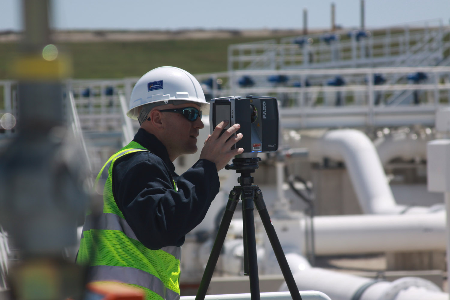
See Figure 1: Laser Scanning in Operation. 3D Laser Scanning provides a tool that enables engineers and designers to think, design and evaluate in a three dimensional world with even greater ease.
What Is 3D Laser Scanning?
3D Laser Scanning is a terrestrial-based data acquisition system that captures high-density 3D geospatial data from large-scale, complex entities. Laser scanners are non-contact devices that incorporate two components for data capture: a laser and a camera as shown in Figure 1. A Class 3R1 laser scans all physical components in its field of view and assigns an XYZ coordinate to each captured point. The laser records the relative position of everything in view, capturing nearly 1 million data points per second1.
The data appears as a “point cloud” which accurately represents the surface of the physical objects scanned as seen in Figure 2.0. The laser captures exact size and shape and converts real world objects into 3D digital representation for storage and manipulation on a computer. The system utilized in subsequent examples, the FARO Focus3D, is extremely accurate, capturing data at ±1.0 mm1 accuracy with a range of up to 120 m1. The scanner can capture a horizontal field of view of 360° with a vertical field of view of 315°, ensuring an almost all-encompassing analysis from a single scan.
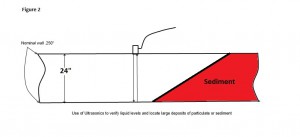
Figure 2 – Laser Scanning Produces a “Point Cloud.” The laser records the distance and texture of everything in view. The data appears as a “point cloud” which accurately represents the surface of the physical objects. The laser captures exact size and shape and converts real world objects into 3-D digital representation for storage and manipulation on a computer.
After the measurement phase of the process is completed, a photo-realistic digital camera then captures a panoramic photograph of the objects within the field of view. The quantitative elements of the laser-captured data are overlaid coincident to the “photographic” element to generate a virtual tour that imbeds 3D information. The resultant virtual tour may be accessed via 3D Scanning Visualization Software supplied by the laser scanner manufacturer or other third-party freeware suppliers. The software allows a user to analyze facilities remotely and quickly gather quantitative information by taking 3D measurements from within the freeware viewer. As well, users may analyze elements of facilities and achieve the majority of benefits of an actual site visit without ever leaving their desk. Chris Anderson, a designer at EN Engineering, suggests that implementation of laser scanning technologies has made his pipeline design team much more efficient:
“The 3D Scanning Visualization Software is an outstanding tool because it allows people to virtually travel to the project site. Traditional photographs often miss important details; scanning visualization files cut down on these misses by allowing users an interactive panoramic view from multiple points, which minimizes the need for additional field verification beyond the initial scanning effort. The ability to measure the images using the integrated point data is also extremely useful, since it makes dimensional data on facilities available without using a CAD program or a tape measure.”
3D laser scanners measure very fine details and capture complex shapes. The scanners are ideally suited for capturing contoured surfaces, complex geometries, and high density of infrastructure where massive amounts measurement data are required to ensure accurate depiction. For complex surfaces, inaccessible components and hazardous environments manual data acquisition is neither effective nor practical.
Benefits Of Laser Scanning On Pipelines. The primary benefits realized by EN Engineering relate to brownfield sites where pipelines and facilities already exist. This is not to say that benefits do not exist for greenfield sites where no infrastructure exists. However, the totality of EN Engineering’s experience has been confined to application in existing pipeline facilities. The use of laser scanning technologies has rapidly demonstrated an array of benefits that have resulted in greater efficiency, greater accuracy, improved safety, improved product output and potential cost savings.
Several of the benefits realized to date include: 1) increased data collection efficiency and accuracy, 2) rapid and accurate development of “true built” documentation, 3) money saved due to improved design accuracy and quality control, and 4) improved project visualization and collaboration.?

Figure 3: Multiple Scans are “Stitched” Together to Generate a Contiguous Data Set. Because of line-of-sight constraints, sites are captured in multiple scans. Scans are then stitched together via a registration process to produces a single contiguous “point cloud.” Registration is achieved by establishing common control points via “registration spheres” that are temporarily deployed across the scan site.
Challenges And Limitations
Laser scanner technology appears to have many applications that can benefit our industry. However, the limitations of the technology should be understood. Laser scanners cannot see “through” objects and must have line-of-sight vision to capture associated data. As an example, a four-sided building must be scanned in multiple scans to capture all associated data. Laser scanners are also limited by distance range and peripheral range. The FARO Focus3D unit is limited by a maximum scanning distance of 120 meters1.
Because of distance, peripheral and line-of-site constraints subject sites are typically captured in multiple scans. The scans are then stitched together by the operator via a registration process that produces a single contiguous “point cloud” that may be utilized for design and analysis. Registration of separate scans is achieved by establishing common control points via “registration spheres” that are temporarily deployed across the scan site.
Separate scans must have three common “registration sphere” or similar targets in common in order to effectively stitch scans together. Figure 3 illustrates that scanner operator locating “registration spheres” on site. The scanner is further limited by wind and excess vibration. As with any precision device, the quality of data capture is improved by maintaining a stable and static position. While the scanner photographic capture is not effective without ambient light, the laser data capture is fully effective without any ambient light.
Finally, caution should be exercised when the laser scanning device is utilized in a potential flammable environment. It is customary to obtain a “hot work permit” when the device is utilized on gas and oil pipeline facilities and may be considered similar to operation of a digital camera.

Figure 4: Overview of 3D Laser Scanning Process. Data generated from the scanner may be seamlessly introduced to most leading CAD platforms. Raw scan output may be distributed to clients in a virtual tour format via freeware point cloud viewers.
The Laser Scanning Process
The laser scan process is rather simple, yet can provide a significant array of product output. Figure 4 demonstrates the typical scanning process and potential product output. The process initiates with capture of data via the laser scanner. Single scan files may be utilized in raw format for manipulation of point clouds via licensed Point Cloud Tools software. Single scan files may also be reviewed via the Scan Visualization Freeware in a virtual tour format with measurement capabilities. Separate scan files must be registered to produce a single contiguous file for further manipulation.
After registration, the point clouds may be deployed directly into most leading CAD platforms from manufacturers such as Autodesk®, Bentley® or Intergraph. Many common CAD programs have been specifically designed to accept “point cloud” data directly into 3D platforms. As well, many third-party software suppliers are providing convenient modules that overlay CAD platforms to greatly facilitate manipulation and modeling of point clouds.
Products such as Kubit PointCloud post-processing software have been utilized by EN Engineering to generate 3D models and greatly facilitate manipulation of point cloud data within AutoCAD. Figure 5 demonstrates usage of Kubit PointSense Plant to rapidly generate 3D piping configurations from laser scan point clouds. Once the scanned data has been merged into a CAD program it can be utilized to generate a variety of product output including: 2D CAD Drawings, 3D CAD Models, or Static Images. It should also be noted that in many cases where only a discrete analysis is required it is not necessary to model point cloud data or produce drawings.
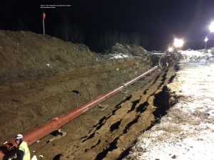
Figure 5: Post Processing Software Allows Rapid Creation of 3D Model. A number of third-party software programs exist that allow efficient conversion of scanning generated point clouds into 3D CAD models.
Pipeline Application Examples
Laser scanning technologies provide significant benefits for a variety of industries. EN Engineering’s business concentrates on the energy industry with specific focus on gas and oil pipelines, storage and production. We have experienced a wide array of applications for laser scanning on gas and oil pipelines and suggest that the benefits are potentially limitless. We have provided a handful of recent examples below that demonstrate how laser scanning has benefitted our clients.
Client: Liquid Petroleum Pipeline Storage Terminal
Issue: Client revised existing pipeline terminal manifold to increase capacity. As-built documentation of facility was poor or non-existent.
Application: The client utilized laser scanning technology to generate efficient and accurate as-built documentation in 3D format to ensure optimum accuracy of the new facility design. The entire existing pipeline manifold was captured via laser scanning and a discrete portion of the system was modeled in 3D format to rapidly produce highly accurate as-built drawings of the interface point between existing and new piping construction. Capture of data required approximately two hours and modeling of the manifold was completed within one day. Inconsistencies in the existing pipe design were revealed due to the extreme accuracy of the laser scanning model. The EN Engineering design team was able to establish “true-built” drawings with unparalleled speed and accuracy and begin the process of designing the new manifold tie-in configuration almost immediately. The design team further benefited from the laser scanning process by being able to “virtually” return to the client site to gather more data without ever leaving the office. This allowed design engineers to develop the new manifold design with great accuracy and no delay.
Upon completion of the new manifold interface, a fabricator utilized the EN Engineering design to manufacture pre-fab modules for “plug in” with the existing pipework at the client site. A greater degree of accuracy and quality control was achieved by scanning the existing facility rather than relying on limited as-built drawings of questionable accuracy. Upon receipt on site, the client was able to seamlessly bolt on the pre-fabricated piping modules without any field rework.
This resulted in reduced downtime and significant savings by returning the facility to service without delay. Lost production time in petroleum projects where energy densities are high can costs hundreds of thousands of dollars per day. The assurance of fit and quality control could have been further enhanced by scanning the pre-fabricated piping modules and mating the pre-fabricated scan to the existing manifold scan. This would ensure perfect fit prior to shipment to site.
Client: Natural Gas Distribution Company (LDC)
Issue: Client required rapid evaluation of clearance of overhead electrical power transmission lines to facilitate egress of construction equipment to job site.
Solution: The gas company utilized laser scanning technology to rapidly and cost-effectively capture relative clearance between electrical transmission lines and topography of gas pipeline as shown in Figure 6. Necessary maintenance and rework of the gas company’s transmission assets adjacent to a major interstate highway was complicated due to overhead electrical power transmission lines. The gas company needed to confirm adequate clearance for large excavation and material handling equipment to ensure safe egress to construction site. The client’s objectives were to efficiently and cost-effectively produce an analysis of the “clearance profile.” A laser scanning operator was able to collect all necessary data related to the overhead transmission lines and a complete topographical analysis within one hour.
Processing and analysis of the scanned data produced an accurate analysis within a day following the scan. The laser scanner met the desired objective safely because it utilized a non-contact technology that enabled measurement of live power lines from ground level. Additionally, the laser scanner was able to capture a complex contour image of the terrain below the power lines. The end result was a very rapid and very cost-effective analysis of the client’s site.

Figure 6: Non-Contact Measurement Captures Infrastructure Without Shutdown. A recent application for a natural gas distribution company required analysis of electrical transmission lines that traversed the gas company’s assets.
Client: Liquid Petroleum Pipeline Storage Terminal
Issue: Client to revise existing pipeline terminal facility to increase capacity, add storage tanks and add pumps. Current as-built documentation of facility is limited to 2D format complicating design analysis.
Solution: Client is conducting large-scale redesign of existing liquid pipeline terminal facility. As-built drawings exist but are limited to 2D format. Based upon previous experience utilizing EN Engineering laser scanning services the client requires 3D “true-built” documentation in order to ensure more accurate, efficient and cost effective execution of the project. Because of the large scale of the project, the sensitivity to design error and construction schedule delays will be greater. Hence, the potential benefits of laser scanning will be greater. EN Engineering personnel were able to capture significant amounts of data in a fraction of the time with greater accuracy than conventional methods. The project is in progress and it is anticipated that laser scanning benefits will be significant. The anticipated costs of laser scanning and subsequent modeling should be easily offset by cost savings during construction of the project.
Client: Natural Gas Distribution Company – Propane-Air Injection Facility
Problem: Existing propane-air injection facility does not have as-built documentation
Solution: Significant revisions to existing propane-air injection facility require creation of accurate and updated as-built documentation to facilitate redesign and creation of a demolition plan. Significant parts of the existing facility will be demolished and rebuilt with optimized design that will include addition of new piping configuration, new heaters, and new vapor retaining wall for increased safety. Creation of highly accurate as-built documentation in 3D format will allow for a more effective demolition plan and ensure efficient installation of the new configuration. The existing piping design is complex and difficult to visualize with current limited 2D as-built documentation. In addition to the new piping design, the client intends to construct a new vapor retaining wall to mitigate risks associated with propane leaks. Grading challenges exist with the current topography that must be addressed in order to produce an effective vapor retaining system. EN Engineering’s design team will capture the topography and segregate it for 3D analysis, to produce an effective grading plan for the new design.
Furthermore, the client wishes to control costs during construction by monitoring quality control on a real time basis. The client will execute regularly scheduled deployment of the laser scanner in order to accurately analyze actual construction vs. the engineering design. Scanning technicians will tie in to survey control via GPS coordinates to mesh existing scan data with new scan data. This will minimize scanning necessary to capture subsequent phases of construction. By scanning on a regular basis, schedule creep can be minimized. This will ensure tracking of actual product against design and minimize rework. Ultimately a high-quality design will be constructed with close adherence to initial project costs and schedule.
The Author
Michael Garvey is vice president of Business Development at Chicago-based EN Engineering, a full-service engineering and consulting firm to the gas and oil pipeline industry. He holds a Mechanical Engineering degree from Purdue University and has more than 20 years of technology implementation, system design, and marketing experience in the gas and oil industry. He can be contacted at (630) 353-4012 or mgarvey@enengineering.com.
Literature Reference
1) “Laser Scanner Focus3D Features, Benefits, & Technical Specifications,” FARO, (May 31, 2011): p. 4.

Comments