
August 2012, Vol. 239 No. 8
Features
Considerations In Designing Multiphase Flow Lines
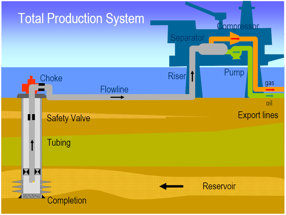
Flow assurance is about ensuring safe and economical transport of raw or processed multiphase mixtures of gas, oil and water from reservoir to reception facilities (Figure 1). As hydrocarbon production now increasingly comes from aging and remote reservoirs, marginal or deep water fields — all with long pipelines transporting commingled fluids under extreme conditions — the need for flow assurance is more crucial than ever.
During multiphase production especially in sour gas producing, hydrate formation and corrosion should be investigated. Additionally, in oil production, corrosion and wax or asphalten formation as unwilling phenomena may be scrutinized. What’s more, in transient studies of production from hydrocarbon reservoirs, sand production should be regarded as an indisputable factor which is defined in erosion velocity. Transient studies should be carried out in order to size the downstream facilities which will be encountering the large amount of liquid or gas. Also, designers should consider the necessary requirements during production and preparation of an operating manual for the best operation by the operators.
Pipeline sizing: One of the most important duties of the flow assurance engineer is finding the suitable pipe size and proper insulation thickness based on related criteria:
Appropriate diameter and pressure drop: Pipeline sizing is a trade-off between available inlet pressure and selection of minimum pipeline diameter for the highest flow rate. To obtain the optimum size pressure drop and pipeline, cost impacts beside flow regime and erosion velocity shall be regarded. At the maximum throughput conditions the mixture velocity should not exceed the erosion velocity limit which is given in API-14E. The pressure gradient in a crude oil/gas multiphase line normally lies in the range of 0.2-2.0 psi/100 feet. However, a more useful means of assessing whether flowing conditions are acceptable is to check whether fluid velocities lie within certain limits. At the low end of the normal throughput range the actual (not superficial) liquid velocity, should ideally be greater than 3 feet/s. This will ensure that sand and water are continuously transported with the liquid phase and not allowed to drop out and accumulate at the bottom of the pipeline. Recommended holdup and pressure drop correlations for horizontal pipelines are achievable in Table 1.
Insulation thickness: Due to some justifications like wax deposition, hydrate formation avoidance and reducing oil emulsion viscosity, the lowest and highest possible flow rate – especially in winter case – is subject to more elaboration for selection of decent finalized thickness.
Choosing a larger diameter leads to much more heat transfer. Hence, further temperature drop inside the pipeline is inevitable. Thus, after evaluating tradeoffs between pipeline diameter and insulation thickness, the optimum size will be determined.
?
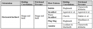
Table 1: Recommended holdup and pressure drop correlations in horizontal pipeline. (Ref: BP Multiphase Design Manual.)
Transient analysis: In single phase, ascending fluid flowrate contributes to higher pressure loss along the pipeline and – in lower flowrates – descending pressure loss is predictable, but multiphase lines have a different story. In higher flowrates, the dominant term in pressure loss equation is friction whereas in lower flowrates gravity plays a key role (Figure 2). Therefore, multiphase flows are not supposed to behave like single phase flows and it is almost certain that higher pressure loss is happening in lower flowrates as well. Actually, in lower flowrates, liquid accumulate and gradually build up in the lowest points, thus liquid content goes up in the pipeline. When there isn’t enough gas to blow out accumulated liquid, undoubtedly pressure is increased in the gas pocket which is located near upstream facilities. Thus, a subtle survey is one of the most crucial factors in order to get reasonably accurate results.

Figure 2: General relationship between pressure loss and flow in multiphase flow-line (assume outlet pressure is given and fixed).
Major studies in order to have a precise and accurate approach for the design of multiphase flow lines and regarding appropriate actions in transmission or reception facilities or any other measures which should have been considered, are as follows:
* Pigging: Pigging operations are performed for inspection, maintenance and removal of accumulated liquid in the low points of pipelines, which create several operational problems such as increasing pressure drop, hydrate formation and corrosion. Pigging a line will create a liquid slug ahead of the pig which normally is followed by a gas bubble. Both make a great deal of challenge for receiving facilities. Basically, the required turn down flow rate for pigging can be considered based on suitable pig velocity. In general, in order to prevent mechanical fatigue and vibration, the speeds usually recommended for routine, conventional, on-stream pigging are 5 to 16 feet/s for liquid lines and 7 to 20 feet/s in gas lines. These figures may differ if the pig is run during construction or commissioning. Final confirmation should be carried out by pig constructor. Slug length and pig velocity in a specific flow rate can be adjusted via some variations in pig performance.
* Ramp up/down: In ramp-up analysis, the flow rate should be set to normal or maximum flow rate from turn down or normal flow rate respectively. By increasing the flow rate, liquid content will be decreased in the pipeline. The effect of increasing the flow rate should be studied over time in order to obtain the best procedure for choosing changing flow rates vs. time, outlet liquid flow rate and determined surge volume in the end of pipeline. In case of flow ramp-down, the flow rate will be decreased from the maximum or normal steady-state flow rate to a lower steady-state flow rate during the specified period.
* Packing/de-packing: To maintain production during a short shutdown of downstream facilities, after closing the valve at the end of the pipeline in receiving facilities, due to the compressibility of multiphase flow, production will be continued. “Packed” in this sense refers to the additional flow that can be stored in the pipeline by increasing operating pressure. Production time before total shut down after valve closing should be calculated based on the MAWP of pipeline. After a packing simulation scenario, the unpacking case should be investigated in order to calculate the maximum liquid slug to downstream facility until it reaches into the steady state condition, required time for pressure and outlet liquid flow rate back into steady state condition.
* Shut down- cool down- start up: During steady-state condition, because of some failures in upstream or downstream, production is supposed to be terminated thusly – flow rate sources need to be stopped (shut-down scenario); after that, the export pipeline may be allowed to cool down and reach ambient temperature (cool-down scenario); subsequently pipeline commissioning and back into normal flow rate is a really vital duty of the operator (start up scenario). Within the shut-down period liquid redistributes due to its gravity and cool down.
Eventually, on start-up, flow-line pressure increases enough to reach the hydrate formation zone; therefore using chemical inhibitors during start up is mandatory. Also, slugging can occur as flow is ramped up. Main issues which are supposed to be investigated during transient analysis for solution of any problems include consideration of the proper insulation due to descending fluid temperature to ambient temperature to avoid touch time passing and wax deposition. Additionally, warm-up times should be investigated to raise fluids temperature to steady-state values and surge volume calculation.
* Slug formation: Slug can form in different ranges of flowrates of oil/gas in horizontal pipes with lots of undulation (hydrodynamic slugs) or in an elevated pipe profile which creates especially in low points (terrain slugs) which originate in wells, or in risers. During transient analysis, the flow regime should specify and — if slug regime is likely — proper action in order to , mitigate slugs is unavoidable. Moreover, the internals of vessels and pipelines shall be designed to withstand all forces during normal operation and upset conditions.
* Slug volume calculation: Separators can be affected by severe operational conditions caused by slug flow. Therefore, it is necessary to use a gas-liquid separator capable of handle the slug flow effects and perform an efficient separation. Slug sizing results should always be treated with caution and slug catchers should be designed with an ample design margin. It is obviously well-known that the potential of lost production arising due to an under-designed slug catcher which usually represents a small fraction of the overall development CAPEX, can be significant. To select the most appropriate slug catcher or separator, simulations should be run for ramp up, shut down-cool down- start up, pigging, packing and unpacking scenario to determine the largest liquid slug volume at the inlet of separator. Generally, for calculation of slug volume, liquid content or liquid hold up in the pipeline should not be considered as slug volume to evaluate storage section of slug catcher which leads to a far-fetched design from reality and wasting of CAPEX. In this regard, the accurate procedure for calculation of the zenith of slug volume is figured out from maximum volume which obtains from subtraction of area under accumulated liquid curve from the total liquid drainage in a specific period of time. The maximum slug volume shall be accounted for between normal and high liquid level alarm.
* Blow down and depressurization: Facilities for operational and emergency pipeline depressurization shall be available at one end of the gas pipeline. The capacity of the blowdown system should be such that the pressure in the pipeline can be reduced as rapidly as practicable, however if the depressurization is too rapid, the temperature drops intensively because of J-T effect . The pipeline must be depressurized in emergency situation or to avoid hydrate formation in the event that the pipeline cannot be restarted immediately following the shut down. Main concerns during depressurization analysis are peak flow rate, minimum pipe wall temperature upstream and downstream of blow-down valve and maximum liquid flow rate which will expose itself to the flare knock out drum.
* Hydrate formation: According to the operating line along the pipeline and hydrate curve in the phase envelope, possibility of hydrate formation is investigated. If formation and growing of hydrate is likely, proper selection of inhibitors to prevent hydrate formation based on economical concern, regeneration of inhibitor and main goal of inhibitor injection should be selected. Hydrate inhibitors can be categorized into three different groups depending on the mechanism of hydrate inhibitors. Kinetic hydrate inhibitors (KHI), Anti-Agglomerants (AA) and thermodynamic hydrate inhibitors (THI) [9]. Beware of dilution of different inhibitor types in production time along pipeline.
* Wax and asphaltene deposition: Initial PVT testing of the reservoir fluids using technologies like light scattering solids detection during expansion to the bubble point, can reveal asphaltene precipitation. WAT is determined by crossed polar microscopy for stock tank fluids. Simulations for the multiphase systems can perform by commercial software and determine wax deposition rate, total wax content and wax thickness in whole pipeline.
* Turndown flowrate: Minimum allowable multiphase fluid flowrate, which the pipeline can handle in stable circumstances, is known as a turndown flow rate which can be demarcated according to the liquid flow rate stability in reception facilities.
Unwilling phenomena are inseparable parts of multiphase production, thus different solutions are already developed to control such events. The most important issues in flow assurance are as follows:
Slugging: Flow regime or flow pattern is a qualitative description of the phase distribution in a pipe. Due to such reasons as different phases in velocities, changing of fluid properties in flow-lines, slippage between phases and different pipeline sizes and inclinations, several flow regimes occupy different parts of flow-map based on superficial liquid and gas velocities.
The worst flow regime in multiphase flow line is slug flow. Slugs can cause problems by creating oscillations in flowrate, leading to flooding at the receiving end, increasing deposits and corrosion. Generally, downward flow and pressure build-up inside the pipeline by different ways cause shrinkage in slug flow region.
Suggested mitigation methods for controlling slug are as follows: gas-lift in order to decreasing bottom hole pressure or gas injection at the bottom of riser; gas injection to reservoir in order to increase reservoir pressure; multi phase pump installation near the wells at manifold; separator and pump installation near the wells and top side choking.
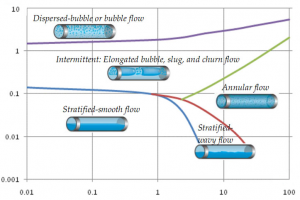
Figure 3: Illustration of steady-state flow regime map for a horizontal pipe (Y axis: Vsuperficial liquid ; X axis: Vsuperficial gas). Ref: “Pipe Flow 2 – Multi phase flow assurance” – Ove Bratland.
* Shut-down followed by cool down and start up: Typically, any subsea well, tie back or flowline at shut-in conditions may be located in the hydrate formation region. Hydrates formation is promoted by high pressure and low temperature. To prevent hydrate formation after shut-down period, different strategies like depressurization, chemical inhibitors injection, heating medium and removal of required water from hydrocarbon are suggested.
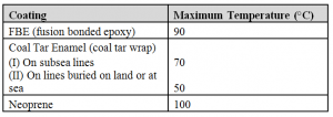
* High temperature related problems: Transportation of high temperature wellhead fluids more than 90°C may give rise to problems in meeting the maximum temperature specification of the pipe coating material. Approximate maximum temperatures for various pipe coatings are given in Table 2.
Table 2: Approximate maximum temperatures for various pipe coatings.
Pipeline corrosion increases with temperature. In some cases it is necessary to cool the fluids prior to entry to the pipeline to reduce corrosion rates to a level consistent with the use of carbon steel pipe work. An alternative to providing cooling offshore is to use corrosion resistant pipe for the initial sections of the pipeline. At some distance downstream of the line, natural cooling in the sea will reduce fluid temperatures to a level where carbon steel pipe can be used.
Asphaltenes and wax depositions can be controlled using following techniques:
1. Production techniques include a) electrical heating of flowlines and riser is an option that is factored in while designing flow assurance; b) reduction of shear; c) minimization of pressure drops in the production facility; d) minimization of mixing of lean feed stock liquids into asphaltic crude streams; e) elimination of incompatible materials from asphaltic crude oil streams (for example, using plastic coated flowlines)
2. Intermittent or continuous injection of chemicals, such as de-asphalted oil, aromatic solvents and antifoulants are suitable to remove asphaltene plugs. Fluid temperatures may drop below the wax appearance point with the result that small particles of wax form. Some of these wax particles are carried along in the liquid and some are deposited on the pipe walls. In fact because the walls of the pipeline are generally colder than the bulk fluid, wax deposition onto the pipe wall may occur while the bulk pipeline fluids temperature is still somewhat above the wax appearance point, hence acceptable margin is necessary to avoiding wax deposition.
Many different types of treating program have been used to control all of the various types of wax deposition problems in different systems include:
1. Hot oiling for flow line cleanup can be cost effective if the paraffin is totally removed and stays in solution in the oil used at separator temperature.
2. Regular pigging is another flow line treatment method which is frequently used based on paraffin deposition rate in the pipeline. It should be noted that although some systems operate below the wax appearance point, their wax deposition rate may be so low that there is no requirement for regular pigging.
3. Solvent or condensate treatments are sometimes inexpensive and can be effective if only lower melting paraffin or congealing oil is the problem but are almost never cost-effective.
4. Chemicals can be applied with any of the above treatment methods and make it more or less cost effective. In practice, paraffin inhibitor is being injected continuously at the first point in the pipeline during all times to provide inhibition of wax formation.
Acknowledgement
The authors would like to express gratitude to National Iranian Oil Company (NIOC) for its support and encouragement in bringing out this work. A list of literature is included in the original manuscript which is available from the author or Pipeline & Gas Journal.
The authors — Seyedamir Hosseini is a Flow Assurance engineer in NIOC, Tehran, Iran. He holds B.Sc. and M.Sc. degrees in chemical engineering from Amirkabir University of Technology (Tehran Polytechnic). He has more than six years of experience in basic and detailed design engineering in production units, gas compressor stations and gas refineries. hosseiny_amir@yahoo.com.
Amir Abbas Jalali Khalilian works at NIOC as an upstream process engineer. He has been involved in the oil and gas industries for more than seven years. He holds the M.Sc. degree in chemical engineering from Iranian University of Science and Technology (IUST). He has experience in basic and detail design engineering in production units and upstream gas and oil pipelines. amirjalali.chemeng@gmail.com.

Comments