
July 2012, Vol. 239 No. 7
Features
Distributed Acoustic Sensing For Pipeline Monitoring
Optical fiber is increasingly being deployed in many upstream and midstream applications. It is now regularly used to provide high bandwidth telecommunications and infrastructure for SCADA, and is being used more to sense pressure, temperature and strain, along buried onshore pipelines, on subsea pipelines and down hole. In this article results are presented from the latest sensing capability using standard optical fiber to detect acoustic signals along the entire length of a fiber.
With Distributed Acoustic Sensing (DAS), an optical fiber is used for both sensing and telemetry. In this article results are presented from the OptaSense® system that when connected to an existing standard single-mode fiber (up to 40 km in length and deployed in a cable next to a buried pipeline), can use the fiber to listen to the acoustic/seismic activity at every 10-meter interval. This article shows that each of the 4,000 independent, simultaneously sampled channels can be used to detect and locate activity within the vicinity of the pipeline and also classify the type of activity through sophisticated acoustic signal processing.
This article includes a look at the ability of the system to use pre-existing fiber optic cables to detect, classify and locate activity such as third-party threats to pipelines, real-time tracking of pigs, gas leak detection and seismic monitoring. We will also briefly highlight how an existing buried optical cable can be used to monitor facilities such as block valve stations, refineries or pumping stations, providing perimeter protection and condition monitoring.
OptaSense is installed on close to 6,000 km of pipeline and other assets globally and the article refers widely to data recorded on field-deployed systems around the world, including how DAS is used to map the impact of earthquakes on pipelines, drawing on recent case studies from Turkey.
Operational Principles
The OptaSense system uses the principle of Coherent Optical Time Domain Reflectometry (C-OTDR) exploiting Rayleigh Backscatter within an optical fiber to measure changes in the acoustic field along the fiber length. Acoustic signal processing allows the source event to be reconstructed and analyzed in real time, located on the fiber and classified according to type.
The unique feature of distributed fiber-optic sensors is that the system utilizes sensing cables that are based on standard fiber-optic cables, to obtain a measurement profile along the entire length of the sensing cable at intervals ranging from 3-10m, depending on the physical size of the system. For a 40-km fiber installation this typically results in 4,000 channels at 10m resolution. There is no specialized sensing point required, thus making it a very simple system for providing total monitoring protection over large distances.
The technology is comparable to the time of flight principle utilized by RADAR technology. Fiber-optic distributed sensing takes advantage of the fact that the reflection characteristics of laser light traveling down an optical fiber vary with temperature, strain, and vibration. The OptaSense system concentrates on the latter although it can also use temperature and strain if required.
There are three types of systems utilized for distributed fiber-optic measurements which are known as Rayleigh, Raman or Brillouin-based systems. This nomenclature is derived, depending on the frequency of signal that is analysed, and the discrete peaks within the electromagnetic spectrum are referred to as the Rayleigh, Raman and Brillouin peaks.
For OptaSense, the sensor consists of a length of standard single mode telecommunications optical fiber (either existing or newly installed) which may be encased in a protective cable. The measuring instrument uses a laser to inject pulses of light into the sensing fiber. A detector measures the reflections from the fiber as the pulse of light travels down its length. Measuring the change in backscattered light against time allows the instrument to calculate temperature, strain or vibration effects on the fiber cable at all positions along the fiber.
Applications
As DAS is sensitive to changes in the acoustic field regardless of source, it is ideally suited to monitoring pipelines for third-party intrusion, and this has been the primary focus for the technology for the past three years. Recent development work, both as part of our on-going research effort and on live installations, has also highlighted the ability of the system to track pig runs, provide seismic data during earthquakes (and subsequently search for changes in the pipeline as a result) and detect gas leaks in buried pipelines.
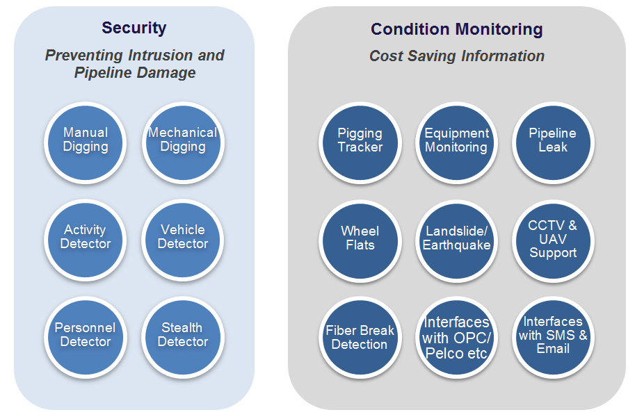
Figure 1 shows the currently deployed capabilities of the OptaSense system, indicating the wide range of operational data which can be obtained using DAS on a single fiber within an optic cable. For each of these software modules, the same OptaSense hardware is utilized. For pipeline integrity managers this data is key, and fiber-optic sensing provides an integrated way of obtaining, using and storing it over the long term.
Third-Party Intrusion Detection
In addition to the integrity management tools previously highlighted, the same-fiber optic cable can be used to protect inline facilities from unwanted intrusion. Figure 2 shows schematically the typical detection ranges for the OptaSense system, although these can be customised according to client requirements.
In the field, distributed acoustic sensing is being widely deployed as the tool of choice for detecting hot taps, unintentional civil engineering works near or on the right of way, vehicle activity and personnel intrusion. The system can provide early warning of an event before the activity gets within damaging range of the asset whilst intelligently filtering out non-threatening activity. This allows the operator to act with confidence on the information provided, preventing harmful incidents from occurring and saving time and money.
Over time an accurate picture of pipeline activity can be built up, often greatly enhancing the user’s knowledge of what occurs on and around a pipeline. Integration with third-party systems such as CCTV can even allow the automatic cueing of cameras to an activity location.

Figure 2: Schematic illustrating the OptaSense pipeline protection capabilities, including typical detection ranges for some common activities.
Pig Tracking
Figure 3 shows a typical waterfall display taken from the software during a pig run on the BTC pipeline managed by BP. As the pig moves along the pipeline it impacts on the girth welds, creating a well-localized acoustic event. This propagates within the pipe itself in both the forward and reverse directions. The chevron pattern created is very distinctive and, crucially, successive chevrons allow the speed and direction of the pig to be accurately located and tracked within the pipe. This capability forms the basis of the pig-tracking service for operators and is performed automatically and in real time via a pig-tracking software module.
When combined with the 10m resolution of the system, DAS offers a robust method for determining the location of a pig within a pipe.

Figure 3: Waterfall trace of a pig moving through the BTC pipeline. The clear chevron pattern is visible and the location of the pig tracked from left to right (as highlighted by the red arrow).
Gas Leak Detection
OptaSense have carried out extensive testing on simulated gas leaks in buried pipelines. OptaSense Gas Leak Detection exploits the short term changes to strain and temperature coupled with the acoustic signal that results from the sudden development of a small leak on a pipeline – all from a single fiber. The use of a signal-fusion technique delivers a more sensitive and reliable result that can be achieved from a single data source.
A monitor image shows the measured change in flow rate, temperature and pressure during a simulated leak. As the pressure rises across the membrane we see a corresponding increase in temperature. Shortly after 50:53 the membrane bursts, simulating a leak event. The pressure quickly drops and stabilizes and we also see a corresponding decrease in gas temperature as it leaks into the ground. Most interesting is the flow from the leak. It is seen that despite a constant orifice and pressure the flow rate fluctuates between 1,500 and 3,500 SLPM. This indicates that the changing conditions around the leak itself prevent a stable flow from being established. The monitor image also shows the recorded acoustic signal at the time of the leak onset. In this case the fiber was 2m offset from the leak event itself.
In practice, OptaSense is able to provide warning of a gas leak in near real time and with excellent on-ground resolution.
Seismic Monitoring
Any OptaSense installation can be used for seismic monitoring by virtue of it being a distributed acoustic sensor. This places us in a unique position as we have a global network of systems which can be used to supply data for early warning as well as monitoring the assets themselves. This may enable emergency shutdown of critical systems in time to prevent further damage.
OptaSense has installed a total of 12 Interrogator Units in Turkey to date, covering over 600 km of the BP-BTC Pipeline. In 2008 we were able to record an earthquake in Turkey as part of a much smaller network and formed the foundations of our seismic monitoring capability. The recent earthquake near Van on Oct. 23, 2011 gave us a unique opportunity to record and analyse a large amount of data across a broad distributed network of acoustic sensors.
There was a network of 12 units installed across Turkey relative to the epicenter near Van (38.78°N, 43.40°E) (http :// www. emsc-csem.org/ Earthquake/ earthquake. php?id=239856# summary) to give an indication of our proximity to the event. Figure 4 shows the recorded waterfall trace for active units in the region, with OPS8 representing the closest unit to the epicenter.
The earthquake itself occurred at 10:41:23 UTC (http :// www. emsc-csem.org /Earthquake/ earthquake.php? id=239856# summary). OPS 4 was offline at this time, but the other 11 units all detect the arrival of a seismic event after this point. Time of flight analysis can be used to determine the epicenter with reasonable precision. More usefully, analysis of the waterfall trace is able to indicate the regions which experienced the most powerful and/or prolonged exposure to the earthquake, and detect if there have been any changes to the operating condition of the pipeline through before/after analysis of the acoustic profile (which can be done with several measurement tools in the system software).
OPS 8 also gives us further information. Being closest to the epicenter it is able to detect the first two aftershocks, despite having been temporarily out of power following the main shock. Detailed analysis also shows the difference in arrival between the pressure wave followed by the much more damaging shear wave
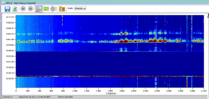
Figure 4: OPS 8 trace showing earthquake event causing power loss in region, followed by two visible aftershocks. Channel 800 also shows a distinct change in acoustic activity when comparing pre- and post- shock levels. As with OPS 5 this is something which the operator can use to guide inspections.
Condition Monitoring
The OptaSense system contains many standard signal processing tools which allow analysis of data beyond basic threshold sensing. One of the key applications for this aspect of the technology is condition or tonal monitoring. Using DAS it is possible to monitor regions for specific frequencies (e.g. an air conditioning unit) and make the user aware if the tonal disappears, indicating a fault. Figure 5 shows this clearly, with the 60Hz signal (and harmonics) disappearing at time T.
In practice, this means that operators can assign a permanent monitor to equipment such as air conditioning units, pumps or backup generators which can provide round the clock situational awareness of their status. Any failure or unexpected shutdown can be alerted on and the duration recorded. Again, the data offered by DAS provides more than a simple alarm trigger.
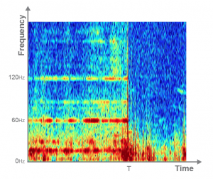
Figure 5: OptaSense condition monitoring of an air conditioning unit. By detecting the cessation of the 60Hz signal at time T we are able to alert the user of a possible fault.
Concluding Remarks
Distributed acoustic sensing has been in use as a third party intrusion detection system for a number of years. However, as the examples in this article show, it is clearly possible to do much more than this with a fiber optic sensor and the right approach to processing the data. Applications such as pig tracking, gas leak detection, seismic and condition monitoring have all been deployed on live systems around the world and are offering improved data right along the chain from operational security to long term pipeline management.
The information and data provided by the DAS system can and should become an essential part of pipeline integrity management decisions over time. Good integrity management is reliant on having good data and DAS provides this for both security and operational purposes, and can be flexibly adjusted to suit the complexity and needs of a particular installation.
This should allow better strategy formulation, resource allocation and performance improvements over time, especially when used in conjunction with or as part of an established PIM process.
Sources
http://www.bp.com/sectiongenericarticle.do?categoryId=9006669&contentId=7015093
http://www.emsc-csem.org/Earthquake/earthquake.php?id=239856#summary
Acknowledgements
This article is based on a paper presented in Feb. 2012 at the Pipeline Pigging & Integrity Conference (Clarion Technical Conferences) in Houston.
The author would like to thank colleagues at OptaSense Ltd. for their assistance in preparing this paper, and also those customers, partners and consultants whose data has been invaluable in providing the examples and case studies contained herein.
Author
John Williams is regional manager for the OptaSense business in the Americas. In the last five years he has delivered Distributed Acoustic Sensing systems covering more than 1,000 miles of pipeline worldwide. Educated at Edinburgh University and Cass Business School in London, he is now based in Houston. Email: john.williams@optasense.com

Comments