
October 2011, Vol. 238 No. 10
Features
Welding Challenges Of 9-Chrome-Moly Steel
With care taken in the welding process, more efficient power-generating system can be operated today with minimum down time for repairs and maintenance. This is due to the development of alloys and knowledge of their performance and behaviors in varying stress and temperature ranges.
The key is in the understanding of these materials by designers and maintenance managers. I have excluded welding engineers from this group because most of the time their knowledge is not in question and often welding engineers are not the final decision makers in these situations.
A “combined cycle power plant” is described as a combination of gas turbine generator (Brayton cycle) with turbine exhaust waste directed to heat boiler and steam turbine generator (Rankine cycle) for the production of electric power. If the steam from the waste heat boiler is used for process or space heating, the term “cogeneration” is the more appropriate term to use meaning simultaneous production of electric and heat energy. Most of the newer plants are designed as or upgraded to co-gen.
The simple cycle gas turbine generator operates as an independent electric power producing unit. The system is a relatively inefficient process because its net heat efficiency at full load is more than 15,000 Btu per kilowatt-hour. Consequently, simple cycle gas turbine generators are used only as standby units or in some applications as a supplementary power unit. The fuel economy of such standby units is of small importance.
A gas turbine releases large quantities of gas through its exhaust system, the temperature of these released gases is more than 480oC (900oF). In a combined-cycle system, these gases are piped to operate a waste heat boiler. These boilers generate high-pressure steam. This superheated steam is then piped to a steam turbine generator. The resulting “combined-cycle” heat rate is in the range of 8,500-10,500 Btu per net kilowatt-hour which is less than a simple cycle gas turbine generator.
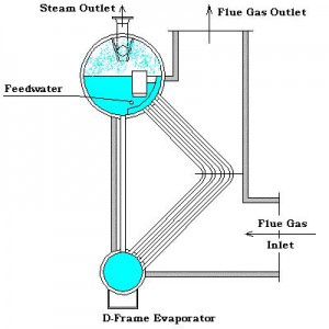
A typical combined-cycle system may have either a single-shaft or multi-shaft configuration. A single-shaft system consists of one each of gas turbine, steam turbine, generator and a heat recovery steam generator. The gas and steam turbines are coupled to a single generator on a single shaft in a tandem arrangement. The single-shaft arrangement gives the operational simplicity, smaller footprint, and lower startup cost, but they are less flexible and have lower functional reliability. Typical heat-recovery steam generator types and layout configurations can be listed as follows: 1) D-frame evaporator, 2) O-frame evaporator, 3) A-frame evaporator. 4) I-frame evaporator, 5) horizontal tube evaporator, and 6) economizer configuration.
On the multi-shaft systems, there is more than one gas turbine-generator and heat-recovery steam generator. They supply steam through a common header to a separate single steam turbine-generator.
The efficient design and operation of these combined-cycle systems requires proper selection of material. The fluctuation in temperature range from lower transformation temperature to austenitizing temperature increases the importance of material selection and the significance of subsequent fabrication, welding and heat treatment. A good design would increase the output and lower cost per unit of energy produced with minimum downtime. In this context, chrome-moly steels, especially 9Cr-1Mo steel and its later variants, have assumed significant importance in the power generation industry.
Nine chrome-moly steels have been used successfully in fossil fuel boilers. In recent years, the alloy P91 and T91in piping and tubing applications, have been used in heat-recovery steam generators.
Properties of 9Cr-1Mo steel alloy that contributed to its use: 1) lower thermal expansion, higher thermal conductivity; 2) improved oxidation resistance, compared to traditional power plant material like ASTM A 335 Grade P-22 or A 213 grade T-22 (2.25Cr-1Mo) ferritic steel and 300 series austenitic stainless steels.
These enhanced properties, prompted designers to use this alloy for steam-plant components. Use of this alloy allowed the choice of relatively thinner walls, thus reducing the stresses induced by thermal cycles.
Further development of these alloys with addition of niobium (Nb), vanadium (V), and nitrogen (N), significantly improved the creep-rupture strength of these alloys. This group of new alloy was later designated as “modified” 9Cr-1Mo and given a new identity by the ASTM as ASTM A213 Grade T91 for tubing and ASTM A 335 Grade P91 for piping often used for headers.
It is important to point out that there is significant difference in application between tubing and piping grades. This difference is based on the following application variables:
1) In piping, the metal temperature does not exceed steam temperature, since steam is the source of heat. In this condition the thermal energy flows from the centerline of the pipe to the pipe’s outside wall.
2) In the superheater and reheater tubes used in the boilers, the hot furnace gas is the source of heat, and thermal energy flows from tube’s outside wall toward its centerline. Due to this subtle and important difference, the tube-metal temperature can be higher than the steam temperature.
Due to these different service conditions, these alloys are used for piping applications in steam service of 590oC (1,100oF). And for tubing applications, up to the operating steam temperature of 565oC (1,050oF).
Most units of the earlier generation used alloy ASTM A 335 Grade T22 (2.25Cr/1Mo) and 304H stainless-steel material for secondary-superheater tubes. Several failures were reported in these tubs. As is expected, majority of these failures had creep damage as the primary mode of failures. Creep is attributed to the excessive metal temperatures. Alloy T91 which has since replaced most of these ASTM A 213-T22 and 304H tubes now presents specific advantages in creep stress conditions.
The advantages of T91 material over T22 and 304 H are: 1) at a given temperature higher allowable stress can be used for design purpose; 2) the T91 alloy has lower coefficient of expansion in comparison to stainless steels; 3) T91 alloy has potential to improve plant efficiency as the turbine-inlet temperature can be raised; and 4) higher allowable stress of the T91 allows designers to select thinner tube walls. This reduces the possibility of thermal-fatigue cracking.
The point to be specifically taken care of in the use of T91 material is its design limitations and it must be acknowledged during design stage: 1) cost of fabrication is higher, due to strict quality control and subsequent stress relieving and heat treatment; 2) procurement of quality material from reputable steel mills; 3) control of design pressure drop through the secondary superheater with the thinner-walled T91 tubes; 4) avoidance of dissimilar metal welds and very careful weld design; and 5) concerns relating to effective quality control.
Welding chrome-moly pipe requires some very specific quality control. Regardless of the grade or the welding process used for welding, maintenance of specific preheat and interpass temperatures cannot be over emphasized. This helps controlled slow cooling of the weld. A range of preheat temperatures from 121-204oC (250-400oF) can be used, depending on the thickness of the material being welded. In-service pipes exposed to temperatures above 450oC (850oF) for an extended period of time often exhibit temper brittleness. It is especially important to preheat these materials when repair is being attempted.
Quality Assurance
Attention to quality assurance is an important factor in accomplishing a successful fabrication and subsequent service and maintenance work.
The degree of attention to quality is the key difference between the work on a fossil-boiler and the combined-cycle experience with P91 and T91 material. In the fossil-boiler industry the designers, fabricators and installers followed all the rules. They operated with conservative design wall thickness, at reasonable steam temperatures of maximum 1,050oF and the material worked fine.
However, welding of P91 and T91 alloy requires a precise heat control during welding and subsequent post-weld heat treatment (PWHT), and the welds between dissimilar metals should be minimized and if it is absolutely necessary it must be very carefully designed. This is irrespective of material thickness or diameter.
In the combined-cycle industry modified 9Cr-1Mo is often seen as a silver-bullet remedy for two major troubles plaguing large heat recovery steam generators (HRSG): 1) the thermal fatigue of thick-walled components, such as main steam piping and superheater headers; and 2) creep damage in the superheaters.
Modified 9Cr-1Mo is effective because the alloy’s mechanical properties allow pressure-containing components to be made of thinner sections, leading to smaller temperature gradients across the wall and reducing time for the metal to reach thermal equilibrium, ultimately resulting in less thermal fatigue.
For example, for a typical HRSG super-heater header upgrade from standard P22 to P91, a reduction in wall thickness of over 50% and the combined weight reduction of all components by about 65% can be achieved.
In welding these modified 9Cr-1Mo alloy, focus must be on control of microstructure. These are very advanced alloys and like most such complex alloys the mechanical properties depend on the creation of a precise microstructure, and the maintenance of that microstructure throughout the component’s service life. With traditional low-alloy steels like Grades 11 (1.5 Cr, 0.5 Mo-Si) and 22 (2.25 Cr and 1 Mo) which operate at lower stresses (allowable stress 15 ksi up to 800oF temperature), the microstructure produced during steel production and fabrication was of only minor importance. In fact, a wide range of microstructures was produced due to a liberal approach to the heat treatment procedures, yet they provided satisfactory service.

Typical Boiler tube welding
As stated earlier, the properties of P91/T91 depend on a precise addition of vanadium (V), niobium (Nb) and nitrogen (N), and a carefully controlled normalizing process to produce a complete phase transformation from austenite into martensite. This produces high tensile strength that has corresponding higher hardness values, and at elevated temperatures high creep resistance. Heat treatment involves a controlled tempering process, to allow the V and Nb elements to precipitate as carbides and carbon nitrides. These carbides and nitrides occupy the voids (at defect sites) in the microstructure. This process is called plugging or pinning and it serves to anchor the defect sites, thereby holding the microstructure in place.
The importance of microstructure and plugging of voids with carbides and nitrides was confirmed by the Onizawa study, presented in 2005 to the European Collaborative Creep Committee (ECCC) conference in London. A series of trial products with controlled variations of V and Nb contents was produced and mechanical tests were conducted on these experimental alloys, both before and after a 6,000-hour aging process. The study confirmed that higher strength and lower ductility were entirely dependent on microstructure which was possible only if proper precipitation of V and Nb as carbides is achieved.
Failure to achieve proper microstructure during original steel production or to maintain it during any welding, fabrication and heat treatment will cause a phase change away from 100% properly tempered martensite or will disrupt the precipitates. Either of these effects will adversely affect the mechanical properties of the alloy.
It may be noted especially in case of HRSG that any repair which is not developed along the correct heat cycle would damage the microstructure of P91/T91 material. Any localized heating or improper post-weld heat treatment (PWHT) can result in failure of these materials.
Selecting Weld Consumables
Several welding processes are used to accomplish good quality welds; they are chosen for the ease of operation and available welding wire or electrode. The selection of welding consumables has important bearing on the end result of a good weld. Some alloying elements, like nickel and manganese in the consumable, have a tendency to bring down the AC1 and AC3 and martensite start (Ms) and martensite finish (Mf) temperatures. This can result in development of untempered martensite in the weld metal and increase the risks of inter critical heat-treating damage. Presence of <1% nickel in the weld metal is often specified by welding engineers. However, the electrodes listed in SFA 5.5 Table-2 for most of the Chrome-Mo electrodes, exception being alloys that contain ? 4% chrome have no such limitations. This conflicts with the base metal requirements of maximum 0.4% Ni. This disconnection adds to the complications of the welding and heat treatment. Many welding procedures have been developed to address this disconnection in weld metal and parent metal composition and its effect on the end result. Welding engineers have specified PWHT temperature range from 732oC (1,350oF) to 774oC (1,425oF), if precise chemical composition of the filler metal is unknown. Alternatively, the PWHT temperature is set in the following two groups: 1) for alloy that has Ni% + Mn% of <1, the PWHT should be 800oC (1,470o F); 2) for alloy that has Ni% + Mn% of between 1.5-2%, the PWHT should be 785oC (1,450oF).

Typical tube-to-tube sheet weld after PWHT.
Intercritical Region/Tempering
The Intercritical Region is described as the temperature range between lower transformation temperature (AC1) and upper transformation temperature (AC3). One significant problem with Grade 91 is post-production exposure to temperatures within this range. When Grade 91 is exposed to this intercritical region, the martensite is partially re-austenitized and the carbon-nitride precipitates are coarsened but do not fully dissolved back into solution. The resulting material has a part austenite/part martensite structure that is unable to lock in the precipitates, resulting in substantially reduced creep-rupture strength. Such reduction in creep rupture strength promotes the fine grain cracks on the parent metal side of HAZ. This is also called type IV cracking. Such a cracking phenomenon is typically associated with P91 material. These cracks often appear in the early stages of the life and at relatively lower operating temperatures. They can subsequently grow sub-surface to some distance prior to breaking through to the surface.
With this material’s relatively longer service in Europe, such cracks have been reported more from European operators than in the U.S. but it has no geographical reason. Therefore, simply put, we are heading in that direction.
Over/Under Tempering
The importance of temperature range maintenance for these materials cannot be over emphasized.
Over-tempering occurs when P91 or T91 components experience prolonged exposure to a temperature below the lower critical transformation temperature (AC1). Due to this, the martensite is unaffected, but the precipitates coarsen with a corresponding loss in creep-rupture strength.
Over-tempering is a lesser risk during fabrication. However, if multiple heat treatment cycles are applied for fabrication of thick-wall components, over-tempering and resulting weakening could become a possibility.
Under-tempering also can jeopardize the high-temperature properties of P91 or T91 since the required precipitation does not go to completion and the precipitates either are absent or are of insufficient size to stabilize the structure. In addition to a loss of creep-rupture strength, risks associated with under-tempering are brittle fracture and stress-corrosion cracking.
To avoid intercritical-region exposure and over-tempering or under-tempering, the component that is heated above 1,470oF, should be re-normalized and tempered in its entirety, or as an alternative, the heated portion could be removed from the component for re-normalizing and tempering and then replaced into the component.
Hardness Testing
Another quality control at the welding and fabrication stage is the mandated testing of hardness. Since at room temperature hardness parallels the material’s room-temperature tensile strength, it is a good indicator of a material’s elevated-temperature behavior.
There is no specified acceptable hardness value by ASME. However, if proper PWHT is carried out, the hardness value should fall within a very tight range of 200-275 HV10 and this ductility will provide sufficient strength at high temperature.
Determining Creep Damage
As we know that creep is the function of diffusion processes, temperature and mechanical stresses are the contributors to creep. Creep causes permanent deformation which can be measured as strain.
This brings out the importance of a method to determine the deformation caused by creep in critical areas like the HAZ of welds. The method is applied as an online measuring tool at the operating temperature. The strain measurements obtained are indicators of the creep rate, which can be used to calculate the actual loss of material life due to creep and – by extension – determine the remaining life.
The method, in principle, is similar to the one used to determine the creep life of catalytic reformer tubes in petrochemical industries. The essentials of this process are to have the base data of the surface conditions ready for comparison with the image obtained later while in service. The base data is the recorded image of a rough surface, used as a baseline data image. Two images, one recorded before and one after loading, are compared by image correlation. By analyzing the results, the strain distribution due to the loading is calculated from relative displacements in two directions.
Author
Ramesh Singh is senior principal engineer with Gulf Interstate Engineering, Houston. He can be reached at rsingh@gie.com.
References
American Welding Society, AWS D10.8-96 “Recommended Practices for Welding of Chromium-Molybdenum Steel Piping and Tubing.”
American Welding Society, “Welding Handbook, 8th Edition, Volume 4, Material and Applications – Part 2.”

Comments