
August 2011, Vol. 238 No. 8
Features
Automatic Multiple Cleaning Pig Launching System Passes Test
A patented automatic multiple pig launching (AMPL) system has been developed and undergone its first commercial use. The system individually launches multiple pigs from a preloaded cassette. The system requires no modification to the existing pipeline launcher because the pig launching process is controlled by a hydraulic system incorporated with the pigs rather than by using complex pipeline on the launcher.
The new system allows a series of pigs to be launched into a pipeline at operator-controlled intervals while minimizing the number of times a pig launcher door has to be opened to access the pipeline. Because the system is hydraulically operated, it does not require any external power supply or additional human intervention. Pipeline pigs are contained within a custom-fabricated cassette designed to suit new or existing pig launching equipment. Unlike other systems AMPL does not require additional valves, launch pins or hydraulic systems to be fitted.
Each AMPL pig has its own hydraulic launch control mechanism that is designed in such a way that the next pig to be launched is only armed when the launcher has been depressurized after the previous launch, and so cannot be launched accidentally. It has an additional safety system in place so that — if the control mechanism fails — no pigs can or will launch.
One benefit of the system is that it can be retrofitted to almost all installed pig launchers, with no adaptation required for the current configuration or the addition of any extra valving or control systems. The only addition is the specially designed launcher basket which can be removed easily if intelligent or any other non-routine pigging is required.
The pig cassette is loaded with AMPL pigs that are interlocked together as part of the fail safe mechanism. To load an AMPL cassette with pre-loaded pigs into a launcher, the launcher is depressurized and the closure door opened. Once the cassette has been loaded into the launcher the closure door is shut. The number of AMPL pigs inserted in the cassette is determined by the length of the launcher and other cleaning and commercial considerations.
One key feature of the system is that the launcher will not be required to be accessed again until all the pigs loaded in the cassette have been launched into the pipeline and a new pigging campaign is required. A launcher which uses the AMPL system therefore minimises launcher interventions.
[inline:Figure 1 – Typical AMPL System Schematic web.jpg]
Figure 1: Typical Automatic Multiple Pig Launching System Schematic.
A schematic of the system is shown in Figure 1. In this case four AMPL pigs are shown pre-loaded within a cassette fitted within a standard pig launcher. Each pig is interlocked with the subsequent pig and is fitted with a trigger mechanism. This mechanism — when engaged — allows fluid to bypass the preceding pigs in the cassette through open bypass ports until the lead pig is reached. This lead pig (the “first pig”) is loaded in the “armed” position, with its bypass ports closed, forming a seal in the cassette. The fluid flow into the launcher then causes the “first pig” to launch leaving the remaining pigs in the launcher. The “first pig” travels along the pipeline functioning as a standard pigging tool.
The launcher can be isolated ready to arm the next pig in the sequence. Arming of the second pig (closure of its bypass ports) is achieved by a combination of the “first pig” launching and a drop the hydraulic pressure in the launcher. This new lead pig (the “second pig”) is now ready to be launched. This launch process can be repeated until all AMPL pigs have been launched. The failsafe mechanism built into the pigs ensures that only the front tool can be armed, ensuring individually controlled pig launching.
The system substantially reduces the costs associated with launching pigs and is particularly beneficial for: 1) standard pipelines that require frequent pigging, 2) remote locations such as desert pigging stations, 3) unmanned platforms that are visited routinely for pigging and maintenance purposes, and 4) subsea launchers/lay down heads requiring ROV intervention between launches.
The use of the multiple pig launching system offers benefits for pipeline operators, specifically with respect to the following key areas:
1. HSE considerations: It is widely recognized within the oil and gas industry that the operation of pig launchers and receivers presents safety hazards to operators. AMPL reduces this risk by reducing the number of interventions.
2. Reduction in labor costs: There is a significant reduction in labor requirements for the pig loading element of the works. Based on conventional pigging on a daily basis there would be a requirement for 365 site visits to reload pigs. In a launcher loaded with a six-pig AMPL system, there would be a requirement for 60 site visits to reload the cassette. A manually operated launcher would still require an operator each day to cycle the valves. Automating the launcher for remote operation would further reduce the labor requirement.
3. Reduction in unaccounted for gas: Prior to loading a pig, the launcher needs to be vented. This results in loss of production and an effect on the environment. An example: Consider a 24-inch pipeline with a six-pig AMPL system running at 1,000 psi, and a requirement for daily pigging. For conventional pig launching the total annual volume released to the atmosphere is in the order of 320,000 cubic feet. Utilizing the AMPL system requires intervention just 60 times. This reduces the release to 19,500 cubic feet/ annum, based on the specific requirement of only requiring a 150-psi reduction in pressure to arm the AMPL pig. This is of financial and environmental benefit to the pipeline operator.
4. Impact on the environment: It is estimated that the above example of a reduction in vented gas results in a four-metric ton carbon equivalent reduction in emissions.
5. Reduction in wear and tear on launcher facilities: A common component failure of any pig trap over time is the moving parts associated with the pig trap closure doors. Hinge mechanisms become worn, seals need constant replacement and door vent screws can become cross threaded and jam. Reduction in door operations will reduce the maintenance associated with these items.
6. Reduction in nitrogen purging: The system has no requirement for nitrogen purging once the pig cassette is loaded into the launcher, thus saving time and money for each pig-launch operation.
Each AMPL system is custom-designed to meet the specifications and requirements of the pipeline. It is essential that accurate pipeline parameters be supplied for this engineered solution to be successful. Within the term parameter the following items need to be considered: 1) pipeline medium, 2) maximum and minimum operating pressure, 3) maximum and minimum operating temperature, 4) maximum and minimum production flow rates, 5) pipeline launcher and receiver geometry, 6) pipeline geometry and features, and 7) frequency of pigging.
The first stage of the design is to produce a pig to negotiate pipeline features and provide the correct level of efficient pipeline cleaning. The second stage of the design involves incorporating the technology within the proposed pig.
The pig design is based on mandrel body pigs with either cups or discs used as the interface between the pipe wall. Depending on the environment and pipeline construction, pigging disc and body material are selected. The maximum number of installable pigs is determined by the length of the existing / proposed pipeline launcher and the frequency of pigging. Additional standard pigging items such as brushes, magnets, scrapers etc. can be fitted depending on the cleaning requirements.
The principle behind the system involves using mandrel body pigs with a high percentage of bypass designed into the pig body (typically >30%). Given the maximum operating flow rates, the design is optimized so that the pigs remain stationary in the launcher under full operating flow. The hydraulic arming mechanism will then be used to close off this bypass, thus allowing the pig to be launched.
However, there is potential for the flow rate to reach its maximum bypass, generating enough flow to create a differential pressure equaling the frictional forces between the pig seals and the pipe wall, launching the pig unintentionally without it being armed. This issue of mis-launch will be controlled using the specifically designed pig cassette which controls the diversion of flow when the pipeline operates at higher flow rates than the pig bypass can accommodate.
The AMPL pigs are armed by utilizing the pipeline pressure within the launcher to close off the bypass. At the point an armed pig launches, the pressure within the arming unit in the subsequent pig is stored. Upon partial depressurization of the launcher the differential pressure between the launcher and arming unit activates the pig (seals the bypass). To prevent activation of the incorrect pig, there is a failsafe mechanism built in to the pigs which only allows the front pig in the train to be activated. The hydraulic circuit in the preceding pigs remains open, allowing the pressure within to drop with the launcher, hence preventing the pig from launching. The pigs are set to arm at a pre-determined drop in pipeline pressure, typically 15Bar.
Whether the launcher is concentric or eccentric, a custom cassette is designed to house the system. The cassette includes a buffer nose seal for sealing in the neck of the reducer. There is also an adjustable backing plate to allow for positional adjustment and to ensure a positive seal. From the specified maximum and minimum flow rates the cassette contains an arrangement of flow ports (varying in size and quantity) to allow launch of armed pigs and restrict the launch of unarmed pigs. If production flow rates were to reduce or increase from the initial specified limits, the cassette could be re-configured to suit the new flow rates.
Each system design undergoes testing before being used in the designated pipeline to ensure that the system performs to specification. The AMPL system has been tested in both liquid and gas systems
[inline:Figure 2 – typical output from CFD software web.jpg]
Figure 2: Typical output from computational flow dynamic (CFD) software.
To better understand the hydraulic behavior of the AMPL pigs and provide the basis for future engineering tools, computational flow dynamic (CFD) models are used to optimize the system design (Figure 2 shows typical outputs). The results of these models are compared with actual test data recorded. The theoretical model used is based around orifice theory, specifically Borda theory. This theory treats the AMPL pig (unarmed, bypassing) as a single long orifice to calculate the flow rate required to generate a desired differential pressure drop. The calculation is based on a derived differential launch pressure and will vary depending on the density of the pipeline product.
In orifice theory, as a fluid passes through a constriction there is a pressure drop from one side to the other. This pressure drop can be used to calculate the flowrate if both the coefficient of contraction and the orifice area are known. Basic hydraulic theory states that the orifice provides a resistance to the flow, which can be calculated from the energy loss over the orifice. The resistance provided by the orifice drops with the square of velocity and each different orifice has a different relationship between velocity and resistance. This theoretical approach has been applied to the AMPL pigs under compressible and non-compressible pipeline flow.
[inline:Figure – 3 Flow Modeling, Theoretical vs Actual.jpg]
Figure 3: Flow Modeling, Theoretical vs. Actual.
The CFD modeling has been refined to give only a 4% error when compared with the actual test data recorded from physical pig testing. The example shown in Figure 3 is a 6-inch AMPL pig which required a differential pressure to launch of 1.5 bar. The shape of the theoretical curve is almost identical to the test data but is slightly offset.
In this case the 6-inch design is restricted to the amount of bypass that can be built into the pig; therefore, if pipeline flow rates run above 0.4m/s the bypass design would not be sufficient to allow product bypass. This would result in uncontrolled multiple pig launches. Therefore, the solution is to engineer the cassette to accommodate the higher flow rate to allow the pipeline flow rate to be increased without affecting the pig behavior. The AMPL cassette design has dedicated flow ports upstream and downstream of the loaded pig train to intentionally split pipeline flow over the pigs / through the pigs. Diverting the flow controls the level of flow that the pigs actually see, preventing unwanted launches occurring.
First Commercial Use. Following up from the development of the AMPL system and a production trial at a UK test facility, the first commercial project was completed in the U.S. The client, a major gas operator, was carrying out a routine of daily pigging runs which required a significant investment in time and resources. The client was drawn by the multiple-launch functionality and the resulting reduction in launcher interventions.
Project Requirements. The client required an AMPL-based solution that could be used to deploy 10-inch pigs in a 27-mile, wet gas gathering system. Details: 1) 10-inch diameter, 27-mile-long wet gas gathering system, 2) daily pigging, 3) operating Pressure: ~ 950 psi, 4) production flow rate range: 4–16 MMscf/d, and 5) black powder removal.

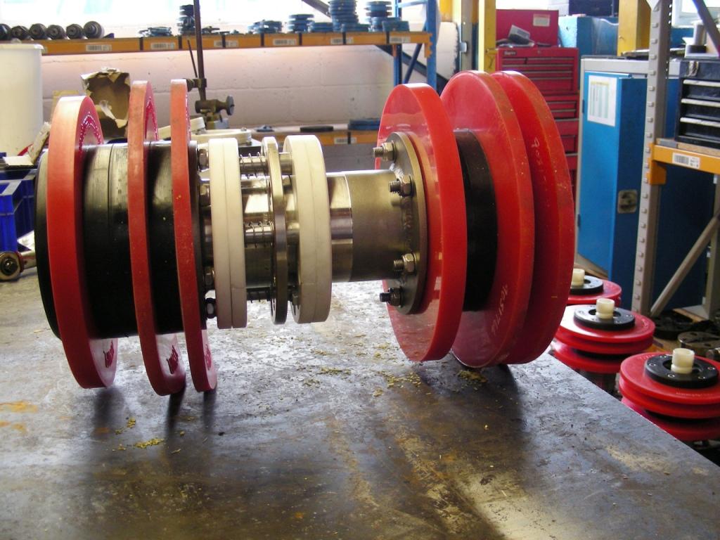
Figure 4: 10-inch Automatic Multiple Pig Launching (AMPL) System Pig.

Figure 5: 10-inch AMPL Dedicated Loading System.
Initially, this involved a thorough evaluation of the pipeline, taking into consideration pipeline flow rates, pressures, temperatures and relevant pipeline geometry. Following the data gathering, the concept system design was generated. A six-pig system, complete with a custom-designed launch cassette and dedicated loading tools (Figure 4 and Figure 5) were manufactured to be retrofitted into the existing launcher. The number of pigs in the system allows launcher interventions to be reduced from 365 to 61 over a year. The system design was optimized through use of CFD and evaluated. A simple test rig was manufactured to replicate onsite conditions to carry out physical testing to evaluate the CFD work.

Figure 6: Received AMPL pigs versus previously used foam pigs.
Additionally the use of solid-bodied AMPL pigs as opposed to the previously run foam pigs, has resulted in a significant increase in the effectiveness of the cleaning with far greater amounts of debris being removed per run (Figure 6), It is anticipated that this may also lead to a reduction in the frequency of pigging required over time. To support the independent launching of the pigs and maximize the labor benefits, the client has invested in fully automating the launching site. This involved adding valve actuators, controlled by a SCADA system, operated remotely from a base away from the launching site. As a result, the labor requirement has been reduced by a factor of six because there is no requirement for daily cycling of valves to launch pigs.
The new AMPL system also shows potential for efficacious subsea employment but space does not permit a discussion here.
Acknowledgements
This article is excerpted from a presentation at the Pipeline Pigging and Integrity Management Conference (PPIM) organized by Clarion Technical Conferences and Tiratsoo Technical and held in Houston Feb. 16-17, 2011. The author wishes to acknowledge and thank BP, Shell, Total, Chevron and Petronas for the support given during the development of the technology and Regency Gas for permission to publish details on the first commercial employment.

Comments